
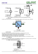

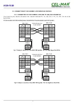


Fig 2. The diagram of the transmitter & receiver Current Loop ADA-1020 Converter
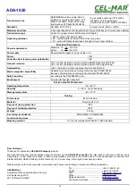
2.5. ISOLATION
The ADA-1020 converter has 3-way, 1kV= or 3kV= galvanic isolation, depend on version described in section
VERSIONS
.
Fig 3. Insulation structure at ADA-1020
3. INSTALLATION
This chapter will show you how to connect ADA-1020 to RS232 device, current loop line and power supply.
In the purpose of minimization of disruptions from environment is being recommended to:
●
apply multipair type shielded cables, which shield can be connected to the earthing on one end of the cable,
●
arrange signal cables in the distance not shorter than 25 cm from powering cables.
●
apply cable of adequate cross-section due to voltage drops for converter powering,
●
not supply converter from power circuit device that generates large impulse interference such as transmitters, contactors,
3.1. ASSEMBLING
The ADA-1020 enclosure is adapted to assembly on TS-35 (DIN35) rail. To install repeater you should mount device on the rail upper
part of the enclosure then press bottom part to to hear characteristic „Click” sound.
3.2. CONNECTION OF DEVICES WITH RS232
Fig 4. RS232 interface signals in DB-9Female
5
ADA-1020
TX-
I= 0 / 20mA
or
I= -20 / +20mA
I
TX+
RX-
R=560
W
/ R=1000
W
Receiver
RX+*
Transmitter - Active
RX+
TX-
I= 0 / 20mA
TX+
Transmitter - Passive
4 DSR not use
The Signals looped on the converter :
1. DTR – DSR – DCD
2. RTS - CTS
2 TX
5 GND
Not use RI 9
Not use RTS 8
Not use CTS 7
Not use DTR 6
3 RX
1 DCD not use
Power Supply
10 - 30VDC
RS232
Current Loop
3-WAY ISOLATION


