20
LED M: Welding position
The abbreviation that appears on the display
U
meets ISO
6947 standards and corresponds to the welding positions
listed in the figure.
The ASME are distinguished by a number plus a letter.
For greater clarity, their symbols are shown below.
LED S: Thickness.
The display
O
lights and displays the set current; the dis-
play
U
displays the thickness corresponding to the cur-
rent. Turning the knob
Y
changes the thickness and the
current will also be adjusted accordingly.
Obviously the thickness and corresponding current will
be measured in relation to the material settings and of
welding position.
LED R: Electrode diameter.
The electrode diameter is displayed as a result of settings
for the material
(LED
L
), position (LED
M:
), and thickness (LED
S
).
The display U shows the recommended electrode
without flashing
; the operator may use the knob
Y
to
also display
other diameters,
but these will be shown
flashing
to indicate that they are not recommended.
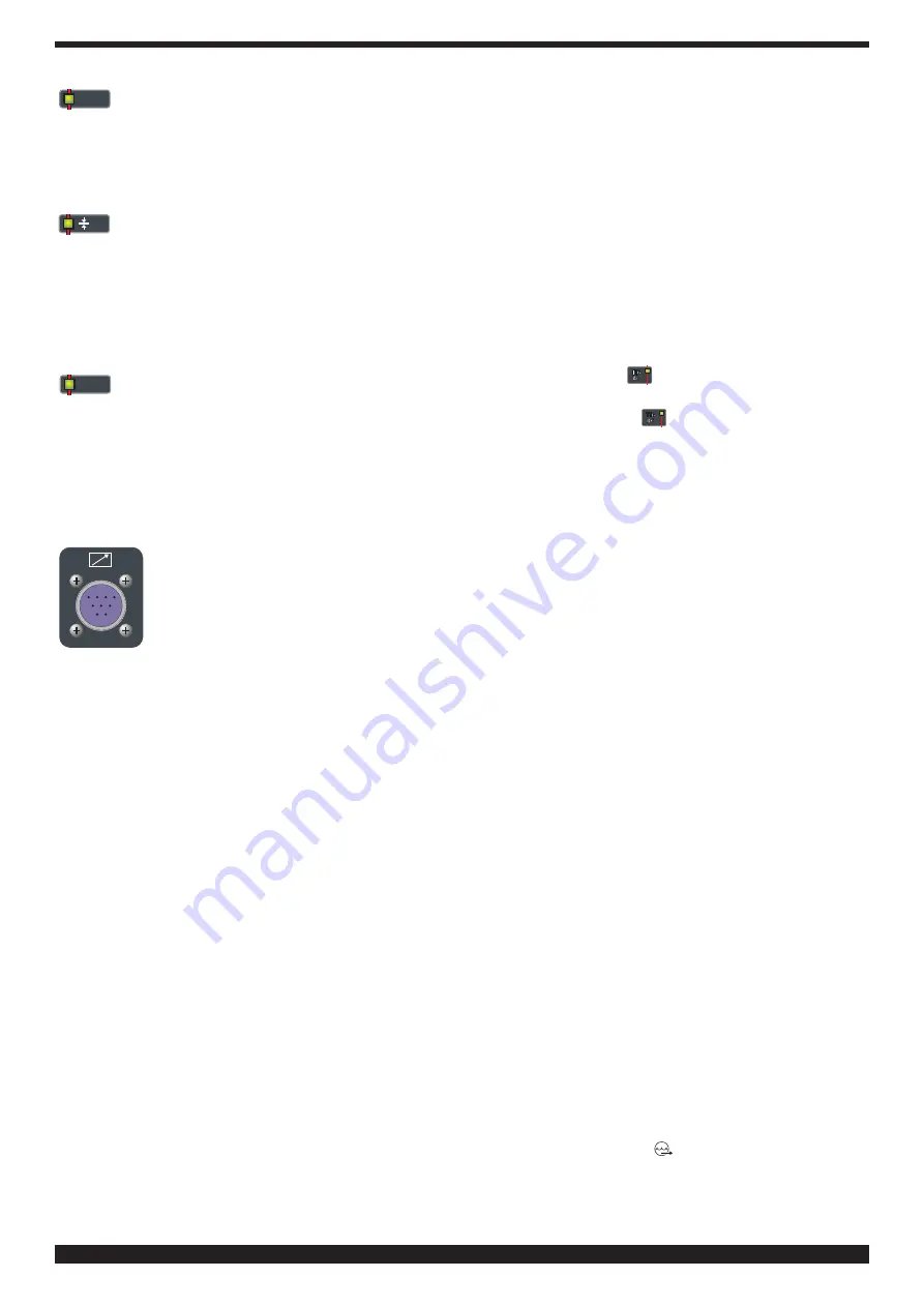
BC - 10-pin connector
This connector is connected to the remote
controls described in paragraph 4.
A clean contact is available between pins 3
and 6 which indicates when the arc is lit
(max. 0.5 A - 125 VAC/ 0.3 A - 110 VDC/1A
- 30 VDC).
3.3. GENERAL NOTES
Before using this welding machine, carefully read the
standards CEI 26-23/IEC-TS 62081. Also make sure the
insulation of the cables, electrode clamps, sockets and
plugs are intact, and that the size and length of the weld-
ing cables are compatible with the current used.
3.4. MMA WELDING WITH COVERED ELECTRODES
- This welding machine is suitable for welding all types of
electrodes, with the exception of cellulosic (AWS 6010).
- Make sure that the switch
BE
is in position 0, then con-
nect the welding cables, observing the polarity required
by the manufacturer of the electrodes you will be using;
also connect the clamp of the ground cable to the work-
piece, as close to the weld as possible, making sure that
there is good electrical contact.
- Do NOT touch the torch or electrode clamp simultane-
ously with the mass terminal.
- Turn on the machine using the switch
BE
.
- Select the MMA procedure by pressing the button
A
,
LED
AW
lit.
To select the type of current suitable for the electrode, fol-
low the instructions below:
• Press knob
AQ
and while holding it down press knob
AP
.
• Hold it down until the display
O
shows the abbrevia-
tion
H2O
.
• Press knob
AP
until display
O
shows the abbreviation
Ø El.
Pos.
MMA
.
• Display
U
shows the abbreviation
DC
direct current-
type of current set by the manufacturer..
• To select the alternating current turn knob
Y
until the
display
U
shows the abbreviation
AC
.
N.B. To exit selection, briefly press the key AQ.
- Adjust the current based on the diameter of the elec-
trode, the welding position and the type of joint to be
made.
- Always remember to shut off the machine and remove
the electrode from the clamp after welding.
If you wish to adjust the Hot-start (LED
D
) and Arc force
functions (LED
C
), see the previous paragraph.
3.5. TIG WELDING
By selecting TIG AC
welding mode you may weld
aluminium, aluminium alloys, brass and magnesium,
while selecting TIG DC
allows you to weld stainless
steel, iron and copper.
Connect the mass cable connector to the positive pole (+)
of the welding machine, and the clamp to the workpiece
as close as possible to the welding point, making sure
there is good electrical contact.
Connect the power connector of the TIG torch to the neg-
ative pole (-) of the welding machine.
Connect the torch connector to the welding machine
connector
BC
.
Connect the torch gas hose fitting to the fitting
BD
on the
machine, and the gas hose from the cylinder pressure
regulator to the gas fitting
BH
.
3.5.1 Cooling unit. (optional for Art.351).
If using a water-cooled torch, use the cooling unit.
Insert the torch cooling hoses in the fittings
BI
and
BL
of
the cooling unit, being careful to correctly place the deliv-
ery and return.
3.5.1.1 Description of protections
- Coolant pressure protection.
This protection is achieved by means of a pressure
switch, inserted in the fluid delivery circuit, which controls
a microswitch. Low pressure is indicated from the flash-
ing message H2O on the display
O.
3.5.1.2 Start-up
Unscrew the cap
BF
and fill the tank (the equipment is
supplied with approximately one liter of fluid).
It is important to periodically check through the slot
BM
that the fluid remains at the “max” level”.
As a coolant, use water (preferably deionized) mixed with
alcohol in percentages defined according to the following
table:
water/alcohol
temperature
-0°C up to –5°C
4L/1L
-5°C up to –10°C
3.8L/1.2L
NOTE If the pump runs with no coolant present, you must
remove all air from the tubes.
In this case shut off the power source, fill the tank, con-
nect a hose to the fitting (
) and insert the other end of
the hose in the tank. Only for Art. 351, insert the pressure
switch connector and the power cord into the sockets
BR
and
BQ
.
Run the power source for approximately 10/15 seconds,
Содержание 366
Страница 123: ...123 Art 366...
Страница 124: ...124 Art 367...
Страница 125: ...125...
Страница 126: ...126 Art 368...
Страница 127: ...127...
Страница 134: ...134 Art 367 368...
Страница 136: ...136 Art 368 05...
Страница 138: ...138...
Страница 139: ...139...
Страница 140: ...140...


