44
REVO PC
User’s manual
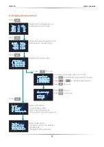
7.2.6 System menu
System Configurations
Alarms enable
= Enable diagnostic alarms (HB or S.C.)
•
H.B.
Heater Break
•
S.C.
Short Circuit
HB Sense (%)
= Set the threshold of resistance that
activates the Heater Break alarm. This setting is in
percentage of the nominal load resistance
HB Delay (sec)
= activation delay of heart break
Thermal alarm Set Point
= Set the threshold of
temperature alarm, when active will appear a message
on display and the output are forced to 0%
Controls menu
Control Kp
= Proportional band factor for each channel
Control Ki
= integral time for each channel
Control Feedback
= Control Feedback for each channel
V
= Voltage feed-back.
The input signal is proportional to the output voltage. This means that input signal
becomes a voltage demand. This control mode compensates the voltage fluctuation
of the incoming line supply.
V2
= Square Voltage feed-back.
The input signal is proportional to the output square voltage. This means that input
signal becomes a power demand. The power remains constant if the load impedance
doesn’t change.
P (VxI)
= Power feed-back.
The input signal is proportional to the power output. This means that input signal
becomes a power demand. The power remains constant also if voltage and load
impedance change.
I
= Current feed-back.
The input signal is proportional to the current output. This means that input signal
becomes a current demand. This control mode maintains the current also if the load
impedance changes.
I2
= Square Current feed-back.
The input signal is proportional to the output square current. This kind of feed-back is
suggested for cold resistance applications.
Power Limit Kp
= Proportional band factor for Power limit
Power Limit Ki
= integral time for Power limit
Pw Lim Stg 1
= Power limit value set in stage1
Pw Lim Stg 2
= Power limit value set in stage2
Pw Lim Stg 3
= Power limit value set in stage3
Содержание REVO PC M-RPC
Страница 2: ......

