REVEX
2PH from 120A to 210A
User’s manual
49
Configurable Inputs and Outputs
The REVEX power controller features two digital inputs, up to two analog inputs and a relay output. Some
models also include an analog output for retransmitting a measured value to other automation equipment.
This section describes the various functions of these inputs and outputs and how they interact with other
features of the power controller.
11.1 Digital Inputs
The REVEX power controller has two optically-isolated, digital inputs that can be connected to control panel
switches or other automation equipment such as a temperature controller or programmable logic controller.
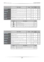
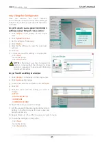
Using Digital In 1 Function and Digital In 2 Function on the hardware menu each digital input can be configured
to perform one of the following:
• Enable:
the power output is off unless this signal is on. If both digital inputs are set to this option, the state
of digital input 2 takes precedence (DI2 Default Configuration).
• Voltage Feedback:
this signal overrides the feedback setting. When this signal is on, the control loop uses
voltage feedback. When the signal is off, the loop reverts to the feedback parameter setting (DI1 default
Configuration).
• Local / Remote:
this signal selects how the set point is set. When this signal is on, the control loop’s set
point is set using the keypad or through communications. When this signal is off, the set point is set by the
an analog input. When a digital input is set to this function, the Local/Remote (L/R) button on the front
panel cannot be used to choose the source of the set point.
• SP Analog In 1 / 2:
this signal chooses which of the two analog inputs is used as the source of the set point
when the remote set point is in effect. When this signal is off, analog input 1 is the source of the remote set
point. When the signal is on, analog input 2 is the source of the remote set point.
• Logging:
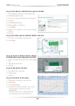
this signal turns data logging on or off. When the signal is on, data is logged. When the signal is
off, data is not logged. When this signal is on, it supersedes the setting of the Logging parameter on the
advanced setup menu.
• Fast Enable (SSR Input):
configuration used for SSR input (see figure in paragraph 8.4.1). This input
configuration allows controlling the unit with a logic signal (ON / OFF) with voltage 4 ÷ 30Vdc 5mA Max (ON
>4Vdc OFF <1Vdc) - 3HZ Max on time min. 100 ms.
• Alarm Reset:
reset the Alarm relay Output if an alarm/s triggered. When this function is selected, and
the digital input is on, the HB alarm resets. If the Digital Input is off and the problem persist, the alarm is
reactivated.
To configure how the power controller uses these signals, see “Digital In 1 Function” and “Digital In 2 Function”
on Paragraph
9.4.4 Hardware menu
.
11.2 Analog Input 1: Set Point
To control the power to the load with a device such as a temperature controller, connect the control signal to
analog input 1.
This input accepts current, voltage and potentiometer signals. The signal is interpreted as set point by
comparing the measured value to the input’s full scale. For example, the set point is 50% when the analog
input detects 5V and the input is configured to receive 0 to 10VdC.
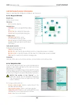
Configure the power controller to recognize the signal with the hardware menu; see “Analog In 1” on Paragraph
9.4.4 Hardware menu
. For instructions for wiring see paragraph 8.4 Schematic
.
11.3 Analog Input 2: Set Point or Feedback
What this input does is user-configurable. Connect an analog signal that indicates:
• An alternate set point signal
• Measured power, voltage or current from an external device used as feedback.
11


