background image

Excalibur 

User Manual 


10 

9M02-7573-A001-EN 
Version 3.0 

4. 

Standard Operator Control Unit (OCU) 

The Excalibur OCU is a lightweight, palm-sized, extremely rugged customizable controller.  

Each OCU is designed to meet a specific control application. Two housing sizes are available that may be 
equipped with 6, 8, 10 or 12 pushbuttons.  

Each pushbutton may have its specific control function identified from a sheet of self-adhesive labels that is 
provided for this purpose.   

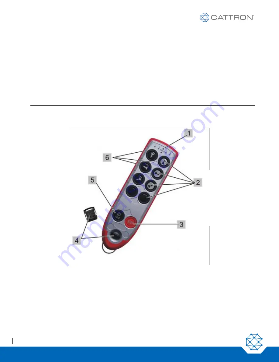
Referring to Figure 1, advanced operational security and configurability is made possible using a removable RFID 
TransKey which, when installed in the OCU, defines and enables the appropriate operating parameters such as 
frequency and address. A label with the ID address is affixed to each TransKey. 

Note:


The OCU TransKey is black, and the MCU TransKey is yellow. Installing an incorrect TransKey 
results in a fault indication and the system will not operate. 


Figure 1: Excalibur 10 OCU, front view 

The 

‘STATUS’ LED (located center top) indicates the operational mode and any error messages. 

The aperture directly under the ‘STATUS’ LED is an Infra-Red port for IR options. 

The four remaining LEDs (two on either side of the ‘STATUS’ LED) indicate either selection information or optional 
Talkback information. 

1. 

‘STATUS’ 
LED 

2.  Two-step 

operating 
pushbuttons  

3.  STOP 
4.  TransKey 
5.  ON/HORN 

pushbutton 

6.  Label fields 

Содержание Excalibur OCU

Страница 1: ...Excalibur OCU User Manual Part 9M02 7573 A001 EN ...

Страница 2: ...es no warranties as to non infringement nor as to the fitness merchantability or sustainability of any Cattron products for any specific or general uses Cattron Holdings Inc or any of its affiliates or agents shall not be liable for incidental or consequential damages of any kind All Cattron products are sold pursuant to the Terms and Conditions of Sale a copy of which will be furnished upon reque...

Страница 3: ...y Pack Removal and Replacement 14 5 3 Charging the Battery 14 5 4 Battery Charging 15 5 5 TransKeys 16 5 6 OCU Switch On Procedure 17 6 OCU Maintenance 19 6 1 Preventative Maintenance 19 7 Operating Frequency Selection 20 7 1 Buttons are used to Program the OCU Frequency 20 7 2 Required MCU Configuration 20 7 3 Changing the RF Channel 21 7 4 Activating the Programming Mode 21 7 5 Selecting the RF ...

Страница 4: ...n the Cranes 36 9 6 Example Configuration 36 9 7 Operating Notes 38 9 7 1 Stop Command 38 9 7 2 MCU Behavior When Switched On 38 9 7 3 Behavior of the Safety Relays 38 9 7 4 MCU Assignment When an OCU is Switched OFF 38 10 Compliance 39 CE Declaration of Conformity 39 RF Compliance 39 Unlicensed Bands 39 Licensed Bands 39 Appendix I Technical Specifications 40 OCU Technical Specifications 40 Batte...

Страница 5: ...nel and damage to equipment WARNING Before attempting to use the remote control system verify the target crane or machine you wish to operate is under the direct command of your OCU This is accomplished by operating a non motion OCU function such as the horn and observing that the horn sounds on the targeted crane or machine Failure to implement the above may result in serious injury or death to p...

Страница 6: ...t any time and do not place yourself or others in a position where this situation may cause you to fall from the equipment Failure to use caution may lead to injury or death WARNING The battery charging unit is designed for use with Cattron Nickel Metal Hydride Ni MH battery packs Other battery packs may explode when charged with this device Failure to comply with this warning will void our warran...

Страница 7: ...e including the CT24 09 CT24 17 Relay MCUs the CCM12 CANopen the J1939 MCU and the MMCU4 which can be configured with other BUS based interfaces such as Ethernet IP PROFINET etc plus relays and Analog and Digital inputs and outputs Talkback optional to LEDs on the Excalibur OCU can be made from either the CCM12 or MMCU4 MCUs The OCU transmits secure data to the MCU where it is decoded and drives t...

Страница 8: ...ive state If the MCU does not receive a valid telegram in this mode for a certain period of time it automatically turns off i e safety relays and command relays open Depending on the application this time varies from 0 5 s to 2 0 s Note In order to ensure optimum communication between the OCU and the MCU the OCU should always ideally be operated with line of sight transmission to the MCU antenna T...

Страница 9: ... every data frame This prevents frozen data and malicious hacking 3 3 System Parameters Many system parameters including the system address and the selected RF channel are programmed within the TransKey this is a removable radio frequency identification device RFID located inside the OCU and MCU It is pre programmed by the manufacturer Note Please refer to the separate Configuration Data documents...

Страница 10: ...ansKey which when installed in the OCU defines and enables the appropriate operating parameters such as frequency and address A label with the ID address is affixed to each TransKey Note The OCU TransKey is black and the MCU TransKey is yellow Installing an incorrect TransKey results in a fault indication and the system will not operate Figure 1 Excalibur 10 OCU front view The STATUS LED located c...

Страница 11: ...as accelerate the first step as hold speed and the released state as decelerate Any function is active only if the respective pushbutton is pressed When the pushbutton is released the function automatically stops Pushbutton 5 is for ON HORN The second step is assigned to the horn that is typically used in a crane application At startup the pushbuttons are checked for the correct off state Figure 2...

Страница 12: ...to the standard OCU Figure 3 Safe T Stop OCU 4 2 General Information The Excalibur OCU is globally compliant when supplied with an appropriate radio module additional certifications may be required for some regions details are available on request It has been designed with the latest generation dual channel electronics and exceeds the Safety Related Systems requirements for ISO13849 Category 3 PLd...

Страница 13: ...e Ni MH battery pack which connects to the underside of the OCU In normal operation a STATUS LED located centrally flashes green at 1 25 second intervals When the battery voltage becomes low the STATUS LED flashes red at one second intervals to alert the operator that the battery pack needs to be replaced or recharged The STATUS LED will also illuminate in a series of red blinking sequences to ind...

Страница 14: ...pack out of its compartment To replace the battery pack carefully insert and lower the battery into the OCU compartment and secure it into position by tightening the rotary latch Figure 4 Battery Pack Removal and Replacement 5 3 Charging the Battery WARNING Do not open the battery charging unit Protect the unit against moisture and rain to prevent a fire hazard or an electric shock Operate the bat...

Страница 15: ...charger and then connecting the charger to the power source The LED will initially be yellow and then it changes to orange when the fast charge starts When the batteries are fully charged the charger enters a top off charge mode before it transfers to trickle charge mode During top off charge the LED will be green with short intermittent yellow flashes When the top off charge is completed the char...

Страница 16: ...g trickle charge Table 1 Charger LED Sequences LED SEQUENCES DESCRIPTION YELLOW Battery not connected YELLOW Battery Analysis phase ORANGE Fast Charge GREEN with YELLOW FLASH Top Off Charge GREEN Trickle Charge GREEN ORANGE Alternating ERROR 5 5 TransKeys WARNING More than one remote control system may be used at around or nearby your operating facility Therefore before inserting a TransKey into a...

Страница 17: ...Fully press the ON HORN pushbutton again The STATUS LED changes to blinking green Note The switch on sequence must be completed within 10 seconds The battery cannot be close to being fully discharged and no other buttons can be depressed or the unit will not start Figure 6 Operating the OCU WARNING Before attempting to use the system verify the target crane or machine you wish to operate is under ...

Страница 18: ... such operation 3 The OCU may be switched off by pressing the STOP pushbutton until the STATUS LED extinguishes In normal operation the STATUS LED flashes green at 1 25 second intervals When the battery voltage becomes low the STATUS LED flashes red at one second intervals to alert the operator that the battery pack needs to be replaced or re charged The STATUS LED will also illuminate in a series...

Страница 19: ...hile the OCU is out of sight 6 1 Preventative Maintenance Preventive on site maintenance is limited to the following Daily Visual Inspection o Before use visually inspect the OCU for cleanliness physical damage and security of external parts screws battery pack switches etc o Regular visual inspections not only mean quickly locating a source of potential problems but also may prevent serious probl...

Страница 20: ...ttons are used as shown in Figure 7 for all Excalibur models The programming mode can be exited at any time by pressing the STOP button In this case the RF channel set prior to the start of the programming remains set UP button Level 1 Channel 1 Level 2 Channel 1 continuously 0 3s channel Transkey RF Channel Level 1 ON button Re activates Transkey RF Channel STOP button Exit without changing the c...

Страница 21: ...higher or next lower RF channel respectively The RF channels are scanned within the cluster Alternatively holding down the second level initiates a fast run approximately 0 3 seconds per channel in order to set the system to the desired RF channel When the desired RF channel has been selected pressing the ON button stores the selected RF channel in the OCU exits the programming mode and switches o...

Страница 22: ...ng the STOP button anywhere in the sequence cancels the RF channel selected exits the programming mode and switches off the OCU When the OCU is switched on again it transmits on the RF channel originally stored in the OCU prior to activating the Programming Mode 7 8 RF Frequency Cluster and Channel Color Code Tables Following activation of the channel change mode on the OCU the set RF channel can ...

Страница 23: ...ge 13 904 4 orange red 14 905 6 orange green 15 906 8 orange orange 16 908 0 red 17 909 2 red red 18 918 8 red green 19 920 0 red orange 20 921 2 red red 21 922 4 red red red 22 923 6 red red green 2 23 903 4 red red orange 24 904 6 red green 25 905 8 red green red 26 907 0 red green green 27 908 2 red green orange 28 909 4 red orange 29 919 0 red orange red 30 920 2 red orange green 31 921 4 red ...

Страница 24: ...range 4 45 903 8 green orange red 46 905 0 green orange green 47 906 2 green orange orange 48 907 4 orange 49 908 6 orange red 50 919 4 orange green 51 920 6 orange orange 52 921 8 orange red 53 923 0 orange red red 54 924 2 orange red green 5 55 904 0 orange red orange 56 905 2 orange green 57 906 4 orange green red 58 907 6 orange green green 59 908 8 orange green orange 60 918 4 orange orange 6...

Страница 25: ...e green 15 433 4275 orange orange 16 433 4525 red 17 433 4775 red red 18 433 5025 red green 19 433 5275 red orange 20 433 5525 red red 21 433 5775 red red red 22 433 6025 red red green 23 433 6275 red red orange 24 433 6525 red green 25 433 6775 red green red 26 433 7025 red green green 27 433 7275 red green orange 28 433 7525 red orange 29 433 7775 red orange red 30 433 8025 red orange green 31 4...

Страница 26: ...green orange orange 49 434 2775 orange red 50 434 3025 orange green 51 434 3275 orange orange 52 434 3525 orange red 53 434 3775 orange red red 54 434 4025 orange red green 55 434 4275 orange red orange 56 434 4525 orange green 57 434 4775 orange green red 58 434 5025 orange green green 59 434 5275 orange green orange 60 434 5525 orange orange 61 434 5775 orange orange red 62 434 6025 orange orang...

Страница 27: ...e Table for 869 MHz Narrow Band LED Color Channel Frequency 1 2 3 4 1 869 7000 red 2 869 7125 green 3 869 7250 orange 4 869 7375 red 5 869 7500 red red 6 869 7625 red green 7 869 7750 red orange 8 869 7875 green 9 869 8000 green red 10 869 8125 green green 11 869 8250 green orange 12 869 8375 orange 13 869 8500 orange red 14 869 8625 orange green 15 869 8750 orange orange 16 869 8875 red 17 869 90...

Страница 28: ...d green 10 419 1750 red orange 11 419 2000 red red 419 2250 red red red 12 419 2500 red red green 13 419 2750 red red orange Not to be used in China Table 7 RF Channel Color Code Table for 447 MHz Band LED COLOR Channel Frequency 1 2 3 4 1 447 8625 orange red 2 447 8750 orange green 3 447 8875 orange orange 4 447 9000 orange red 5 447 9125 orange red red 6 447 9250 orange red green 7 447 9375 oran...

Страница 29: ...h button to the first stage the interference field strength is displayed via the STATUS LED STATUS LED Signal Strength Recommendation Red Orange High 70 to 30 dBm Medium 100 to 70 dBm Select another RF channel Green Low 120 to 100 dBm Channel is good 7 9 2 Acoustic Interference Field Strength Output By pressing the field strength button to the second stage the interference field strength is output...

Страница 30: ...an be accepted or the next channel proposal on the list can be selected 7 10 1 RF Channel Change in Scan Mode While the OCU is in programming mode pressing the scan button 2nd stage creates a list of RF channels where no or little noise field strength has been measured The following shows the operation and the sequence of this function Figure 9 Scanning Method ...

Страница 31: ...e selection 0 13 8 2 Storing the Last Selection Via the Electronic Selection Switch Storing the last selection via the electronic selection switch and reloading this selection on switching the OCU on is preset in the Transkey 8 3 The Electronic Selection Switch Sequence The different sequences are configured via the TransKey Switching to different hoists takes place each time the button S71 S73 wi...

Страница 32: ... sequence 11 13 for lifting gear I II Lifting gear sequence 10 for lifting gear I II S73 12 Button OCU Lifting gear sequence 6 9 for lifting gear II Lifting gear sequence 11 13 for lifting gear III IV S73 and S74 second step Enable sequence 10 S67 10 Button OCU Lifting gear sequence 0 5 for lifting gear I II Lifting gear sequence 6 9 for lifting gear I Lifting gear sequence 11 13 for lifting gear ...

Страница 33: ...X X X X X X X X X X X X X X X X X X X X X X X X X X X X X X X X X X X X X X X X X 13 INDEPENDENT BUTTON SELECTION A B A 14 ONE BUTTON FOR UP TO 4 HOISTS 8 9 INDEPENDENT BUTTON SELECTION ON OFF ONLY ONE HOIST AT A TIME 10 RIGHT BUTTON MUST BE DEPRESSED AS AN ENABLE 11 12 INDEPENDENT BUTTON SELECTION A B BOTH 2 3 SEQUENTIAL A BOTH B 4 5 SEQUENTIAL A B A 6 7 INDEPENDENT BUTTON SELECTION ON OFF 10 BUT...

Страница 34: ... X X X X X X X X X X X X X X X X X X X X X X X X X X X X X X X X X X X X X X X X 13 INDEPENDENT BUTTON SELECTION A B A 14 ONE BUTTON FOR UP TO 4 HOISTS 8 9 INDEPENDENT BUTTON SELECTION ON OFF ONLY ONE HOIST AT A TIME 10 RIGHT BUTTON MUST BE DEPRESSED AS AN ENABLE 11 12 INDEPENDENT BUTTON SELECTION A B BOTH 2 3 SEQUENTIAL A BOTH B 4 5 SEQUENTIAL A B A 6 7 INDEPENDENT BUTTON SELECTION ON OFF 12 BUTT...

Страница 35: ... an electronic MCU selection switch and in this case the current position of the switch is indicated using two LEDs 1 2 1 2 9 3 Request Function The selected MCUs must be requested by the OCU All the MCUs assigned to a selected switch position are always requested together MCUs assigned to an OCU as a result of a previous request remain permanently assigned to that OCU even if additional MCUs are ...

Страница 36: ...e same time Sequential releasing of multiple MCUs e g first MCU 1 and then MCU 2 etc is also possible Keep the Release button pressed until the status indicator on the crane indicates the desired status Depending on the system configuration three different types of release are available and can be used individually or in any combination o Manual release only by pressing the Release button o Automa...

Страница 37: ...Excalibur User Manual 37 9M02 7573 A001 EN Version 3 0 Figure 12 Multi control mode Figure 13 Single control mode ...

Страница 38: ... an OCU is Switched OFF If an OCU A is switched off without having released the MCUs assigned to it one of the following two events will occur Those MCUs remain assigned to OCU A and thus cannot be requested by a second OCU B or depending on the configuration the MCU assignment is cancelled automatically after a specific period i e automatic release In systems without automatic release the assigne...

Страница 39: ... of the FCC Rules These limits are designed to provide reasonable protection against harmful interference This equipment generates uses and can radiate radio frequency energy and if not installed and used in accordance with the instruction manual may cause harmful interference to radio communications Operation of this equipment in a residential area is likely to cause harmful interference in which...

Страница 40: ...tely 10 22 oz 290 g for 6 and 8 button variants Approximately 12 35 oz 350 g for 10 and 12 button variants DIMENSIONS 7 08 x 2 52 x 1 53 in 180 x 64 x 39 mm for 6 and 8 button variants 9 25 x 2 52 x 1 53 in 235 x 64 x 39 mm for 10 and 12 button variants HOUSING Styrene Butadiene plastic standard colors silver red with integrated drop protection alternates available OPERATING TEMPERATURE 4 ºF to 14...

Страница 41: ...n Switch the OCU OFF then ON again Replace charge battery pack If fault persists investigate fault Change OCU board Return OCU for repair 5 flashes Switch on sequence not performed correctly Switch the OCU OFF then ON again 6 flashes Fault during reading of command initiator Investigate fault Change OCU board keyboard Return OCU for repair 7 flashes Incorrect RF module or RF module incorrectly con...

Страница 42: ...Excalibur User Manual 42 9M02 7573 A001 EN Version 3 0 Appendix III Configuration Sheets Example Configuration Sheet for System Model 983127 ...

Страница 43: ...Excalibur User Manual 43 9M02 7573 A001 EN Version 3 0 Example Configuration Sheet for System Model 983128 ...

Страница 44: ...Excalibur User Manual 44 9M02 7573 A001 EN Version 3 0 Example Configuration Sheet for System Model 983129 ...

Страница 45: ...Excalibur User Manual 45 9M02 7573 A001 EN Version 3 0 Example Configuration Sheet for System Model 983130 ...

Страница 46: ... document is subject to change without notice Cattron Support For remote and communication control systems support parts and repair or technical support visit us online at www cattron com contact Cattron North America Inc 655 N River Rd NW Suite A Warren OH 44483 9M02 7573 A001 EN Version 3 0 ...

Отзывы: