background image

Page

TMO - PS11061AENAA01

Vehicle-Mounted TPM700 Technical Manual


2-2 14/10/08


Description

This document is the 

proper

ty of

 E

A

D

S

 S

e

cur
e Networ

ks

 and should not be

 copied or

 circulated without pe

rmission

Ce
 docu

m

ent est la pr

opriété de 

E

A

D

S

 Secur

e Networ

ks et

 ne d

oit pa

s êtr

e repr

oduit ou communiqué sans a

utorisation

1

2

3

4

5

Figure 2.1 shows a diagram of the new vehicle assembly.

Figure 2.1

VEHICLE ASSEMBLY INSTALLATION DIAGRAM - HT8333

Figure 2.2

VEHICLE ASSEMBLY INSTALLATION DIAGRAM - HT8338

J1

J2

C2

C1 C1

X1

X2

C3 P1

X3

X4

BER bracket

BER

Antenna*

Antenna 
cable*

Power cable*

Power 

supply filter

Accessory 
cable 
(HG5115)*

UDT 
option*

Digital 
input/output 
option*

Audio accessory option*
. PTT
. End a call
. Activate horn

System cable 

BER - CH (HG5114)

External LS 
option*

(HG5116)

CH

CH cradle

LS-

microphone

*Equipment not supplied by manufacturer

Power supply*

J1

J2

C2

C1 C1

X1

X2

C3 P1

X3

X4

C4

C3

BER bracket

BER

Antenna*

Antenna 
cable*

Power cable*

Power 

su

pply filter

External 
LS option*

System cable

BER - CH (HG4354)

External LS configuration 
plug (HT8342)

CH

CH cradle

*Equipment not supplied by manufacturer

Power supply*

UDT 
option*

LS-

microphone

Содержание TPM700

Страница 1: ...Ch13 Ch14 Total 4 10 4 10 2 52 4 88 Mots clefs Avertissement En l absence d indication contraire cette nouvelle édition annule et remplace l édition précédente qui doit être détruite ainsi que les copies faites à vos collaborateurs La Version Édition précédente n est pas obsolète Préparé par Date Approuvé par Date Autorisé par Date AUTEUR F DORVAL 14 10 08 DOCUMENTALISTE N APPERT RESPONSABLE TRADU...

Страница 2: ...LICABLES Procédure de Réalisation de la Documentation Exploitant PMR GEN PCD 00072 01 06 FR Maîtrise de la Documentation Exploitant de PMR F PMR GEN PCD 00014 05 01 FR Guide de Rédaction d un Document Exploitant PMR GEN MEG 00055 01 01 FR DOCUMENTS DE RÉFÉRENCE Manuel Technique de la Configuration Radio Moto MC2 TR APP 00081 01 01 01 ...

Страница 3: ...cal Manual MC2 TR APP 00094 Page TMO PS11061AENAA01 01 01 EN 14 10 08 iii PAGE D ÉVOLUTION INTERNE VERSION DATE COMMENTAIRES CHAPITRE CONCERNÉ AUTEUR 01 01 EN AENAA01 14 10 08 Traduction du document 01 01 FR 0 à 5 P AVERY F DORVAL ...

Страница 4: ...Page MC2 TR APP 00094 Vehicle Mounted TPM700 Technical Manual iv 14 10 08 01 01 EN TMO PS11061AENAA01 PAGE LAISSÉE INTENTIONNELLEMENT BLANCHE ...

Страница 5: ...Vehicle Mounted TPM700 Technical Manual TMO PS11061AENAA01 10 2008 ...

Страница 6: ...ment est la propriété de EADS Secure Networks et ne doit pas être reproduit ou communiqué sans autorisation Page TMO PS11061AENAA01 Vehicle Mounted TPM700 Technical Manual 0 2 14 10 08 Preliminaries EADS Defence and Security Metapole 1 boulevard Jean Moulin CS40001 78996 Elancourt Cedex France Email PMRsupport eads com ...

Страница 7: ...n Vehicle Mounted TPM700 Technical Manual TMO PS11061AENAA01 Page Preliminaries 14 10 08 0 3 DOCUMENT AMENDMENTS VERSION DATE COMMENTS CHAPTER UPDATED AENAA01 14 10 08 Creation of the document For the scope of application see Section 1 3 Document 0 0 to 5 To supplement our efforts in developing this document we invite readers to send us their corrections and suggestions for improvement on an Anoma...

Страница 8: ...doit pas être reproduit ou communiqué sans autorisation Page TMO PS11061AENAA01 Vehicle Mounted TPM700 Technical Manual 0 4 14 10 08 Preliminaries BREAKDOWN OF DOCUMENT CHAPTER VERSION DATE CHAPTER VERSION DATE Chapter 0 AENAA01 14 10 08 Chapter 1 AENAA01 14 10 08 Chapter 2 AENAA01 14 10 08 Chapter 3 AENAA01 14 10 08 Chapter 4 AENAA01 14 10 08 Chapter 5 AENAA01 14 10 08 ...

Страница 9: ... 2 3 2 2 1 Control Head Figure 2 3 2 3 2 2 2 Transmitter receiver unit BER Figure 2 4 2 5 2 2 3 Simplified BER bracket Figure 2 5 2 6 2 2 4 Cables 2 7 2 3 SPECIFICATIONS 2 7 2 3 1 Hardware specifications 2 7 2 3 2 Electrical specifications 2 7 2 3 3 Technical specifications 2 8 2 3 4 External interface specifications 2 8 2 3 5 Environmental specifications 2 8 2 4 FUNCTIONAL DESCRIPTION 2 9 3 USE 3...

Страница 10: ... ne doit pas être reproduit ou communiqué sans autorisation TABLE OF CONTENTS 4 3 LOGISTICS INFORMATION 4 5 4 3 1 Operators 4 5 4 3 2 List of replaceable sub assemblies fuses and cables 4 5 4 3 3 Availability 4 6 4 3 4 Support equipment 4 7 4 4 PREVENTIVE MAINTENANCE 4 8 4 4 1 Presentation 4 8 4 4 2 Schedule of preventive maintenance operations 4 10 4 5 CORRECTIVE MAINTENANCE 4 15 4 5 1 Presentati...

Страница 11: ...TABLE 4 1 LIST OF REPLACEABLE SUB ASSEMBLIES 4 5 TABLE 4 2 LIST OF REPLACEABLE FUSES 4 5 TABLE 4 3 LIST OF REPLACEABLE CABLES AND ACCESSORIES 4 6 TABLE 4 4 CONSEQUENCES OF A FAILED SUB ASSEMBLY ON THE VEHICLE ASSEMBLY 4 6 TABLE 4 5 LIST OF TEST EQUIPMENT AND ACCESSORIES 4 7 TABLE 4 6 LIST OF MEASURING EQUIPMENT AND ACCESSORIES 4 7 TABLE 4 7 LIST OF TOOLS 4 7 TABLE 4 8 LIST OF PRODUCTS AND CONSUMAB...

Страница 12: ...SEMBLY INSTALLATION DIAGRAM HT8333 2 2 FIGURE 2 2 VEHICLE ASSEMBLY INSTALLATION DIAGRAM HT8338 2 2 FIGURE 2 3 CONTROL HEAD 2 4 FIGURE 2 4 BER 2 5 FIGURE 2 5 SIMPLIFIED BER BRACKET 2 6 FIGURE 4 1 MAINTENANCE ORGANISATION 4 3 FIGURE 4 2 LAYOUT OF A P SHEET 4 9 FIGURE 4 3 LAYOUT OF AN A SHEET 4 16 FIGURE 4 4 LAYOUT OF AN E SHEET 4 29 FIGURE 4 5 REPLACING THE CH 4 33 FIGURE 4 6 REPLACING THE BER 4 37 ...

Страница 13: ...ET P 2 MANUAL CORRECT OPERATION TESTS 4 13 SHEET A 1 POWER SUPPLY FAULT 4 19 SHEET A 2 NO DISPLAY 4 21 SHEET A 3 THE CH DISPLAYS AN ERROR MESSAGE 4 23 SHEET A 4 POOR COMMUNICATION QUALITY 4 25 SHEET A 5 ACCESSORY FAULTS 4 27 SHEET E 1 REPLACING THE CH 4 31 SHEET E 2 REPLACING THE BER 4 35 SHEET E 3 REPLACING THE POWER SUPPLY FILTER 4 39 SHEET E 4 REPLACING THE SIMPLIFIED BER BRACKET 4 41 SHEET E 5...

Страница 14: ... 08 Preliminaries This document is the property of EADS Secure Networks and should not be copied or circulated without permission Ce document est la propriété de EADS Secure Networks et ne doit pas être reproduit ou communiqué sans autorisation PAGE INTENTIONALLY LEFT BLANK 1 ...

Страница 15: ...chapter provides general information including abbreviations definitions etc Chapter 2 Description This chapter gives the new vehicle assembly an installation diagram the various associated accessories their characteristics and the functions they provide Chapter 3 Use This chapter describes in the form of sheets the operating procedures likely to be carried out startup shutdown etc Chapter 4 Maint...

Страница 16: ... Operating Manual PS10517 or PS10506 4 Illustrated Spare Parts Catalogue O Level Maintenance TETRAPOL Networks TDM and IP PS9939 There may be Technical Bulletins accompanying this document and the documents above See Document 0 for their references 1 4 ABBREVIATIONS BER Boîtier Émission Réception Transceiver unit CH Control Head GPS Global Positioning System IDR Independent Digital Repeater IP Int...

Страница 17: ...he workshop by end users or general maintenance personnel using standard or easy to use maintenance tools Example Replacement of a terminal battery connector I level Intermediate This level covers fault isolation and replacement of defective sub assemblies complex fault and failure isolation carried out at a regional level by specialists using specific tools Example Replacement of a board in a ter...

Страница 18: ...troduction This document is the property of EADS Secure Networks and should not be copied or circulated without permission Ce document est la propriété de EADS Secure Networks et ne doit pas être reproduit ou communiqué sans autorisation 1 2 3 4 5 PAGE INTENTIONALLY LEFT BLANK 12 ...

Страница 19: ...onomous mobile terminal connected to the PMR network via a radio link The terminal is a complete assembly designed to be installed in a vehicle and can be used while the vehicle is stationary or in motion The new vehicle assembly consists of a BER transmitter receiver unit a simplified BER bracket a control device called a CH Control Head an antenna in the system frequency range supplied locally o...

Страница 20: ...BLY INSTALLATION DIAGRAM HT8338 J1 J2 C2 C1 C1 X1 X2 C3 P1 X3 X4 BER bracket BER Antenna Antenna cable Power cable Power supply filter Accessory cable HG5115 UDT option Digital input output option Audio accessory option PTT End a call Activate horn System cable BER CH HG5114 External LS option HG5116 CH CH cradle LS microphone Equipment not supplied by manufacturer Power supply J1 J2 C2 C1 C1 X1 X...

Страница 21: ...l Head Figure 2 3 The Control Head which is mounted on the dashboard provides the man machine interface The front panel of the Control Head comprises the send item 14 and end call item 6 keys the directory selection key item 16 a transmit LED item 4 an emergency key item 8 a key for switching to VePeaWay mode depends on project item 13 a display item 3 the softkeys items 16 to 18 The keys and disp...

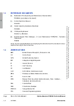
Страница 22: ...ejected 7 Alphanumeric keypad 8 Emergency key 9 Captive screws 10 Activate deactivate loudspeaker horn 11 Access the selector long press 12 Phone call long press 13 VePeaWay mode depending on project short press 14 Send a call accept a call 15 Green LED terminal registration 16 Right soft key 17 Shortcut button 18 Left soft key 19 Sub D 15 pin female speaker microphone socket 20 Sub D 9 pin female...

Страница 23: ...rge of the Control Head from the vehicle battery audio amplification and management of accessories and peripheral devices such as the speaker microphone loudspeakers and UDT The BER item 1 consists of the following items a SUB D 9 pin female socket item 2 protected by a sealed captive plug and used for downloading the software to the BER a SUB D 25 pin male socket item 3 providing the operating li...

Страница 24: ... simplified BER bracket item 7 is fitted with a power supply filter item 5 consisting of a cable fitted with a female 2 pin AMP 2 connector item 3 for connecting the power supply cable item 4 a cable fitted with a male 2 pin AMP 2 connector item 2 for connecting the system cable female 2 pin AMP connector item 1 The simplified BER bracket is mounted in the vehicle boot by means of four fixing boss...

Страница 25: ...e connector via a filter assembly mounted on the simplified BER bracket 2 2 4 2 Accessory cable The system cable connects the CH to the BER and to the accessories external loudspeaker data terminal 2 3 SPECIFICATIONS 2 3 1 Hardware specifications Dimensions h x l x d 58 x 188 x 39 mm Dimensions of BER h x l x d 220 X 43 X 168 mm Dimensions of simplified BER bracket h x l x d 220 x 65 x 240 mm Weig...

Страница 26: ...etween 5 MHz and 20 MHz for WB BERs Step channel spacing 10 kHz or 12 5 kHz Reception sensitivity 119 dBm for WB BERs 2 3 4 External interface specifications 2 3 4 1 Power supply input Source 10 8 V to 15 6 V at the power supply cable end battery side 2 3 4 2 Antenna output Socket female TNC Impedance 50 Ohms 2 3 5 Environmental specifications 2 3 5 1 Ambiant temperature for use The ranges for use...

Страница 27: ...s These functions are provided by the wide band BER box For the vehicle assembly to be operational the wide band BER must be loaded configured and customised by the TPS see section 1 3 Document 3 Loading involves saving the operating software for the project in the wide band BER s memory This software provides access to all the functionalities offered by the PMR system Configuration involves enter...

Страница 28: ...Description This document is the property of EADS Secure Networks and should not be copied or circulated without permission Ce document est la propriété de EADS Secure Networks et ne doit pas être reproduit ou communiqué sans autorisation 1 2 3 4 5 PAGE INTENTIONALLY LEFT BLANK 2 ...

Страница 29: ...RTING UP SHUTTING DOWN 3 2 1 Starting up Note The BER must first be loaded with the project operating software configured and customised by the TPS for it to be operational and to be able to access the PMR network services see section 1 3 Document 3 Press the key Figure 2 3 item 2 on the CH briefly The CH emits an information beep The welcome screen is displayed for two or three seconds Use of the...

Страница 30: ...8 Use This document is the property of EADS Secure Networks and should not be copied or circulated without permission Ce document est la propriété de EADS Secure Networks et ne doit pas être reproduit ou communiqué sans autorisation 7 1 2 3 4 5 PAGE INTENTIONALLY LEFT BLANK 3 ...

Страница 31: ... distribution safety precautions The vehicle assembly must be supplied with 13 2 V DC from the vehicle battery The power supply is protected by a 7 5A jumper fuse fitted upstream of the simplified BER bracket on the power supply cable 4 2 GENERAL 4 2 1 Organisation System maintenance comprises those operations required to maintain a system in a given state or to return it to that state or to resto...

Страница 32: ...ssories O U level O User O W level O Workshop I level Intermediate All the operations described in this document are O W level 4 2 2 Types of maintenance Maintenance operations on the vehicle assembly are divided into two types Preventive maintenance This is carried out at pre determined intervals or in accordance with prescribed criteria with the aim of reducing the likelihood of a breakdown or a...

Страница 33: ...e 4 1 MAINTENANCE ORGANISATION I level maintenance Preventive maintenance scheduled Fault message in which the operational state is shown on the screen Corrective action OK Locate the fault A sheet Fault located OK Preventive maintenance completed Yes No No Yes No Yes O W Workshop level O U User level Corrective maintenance completed Replace the faulty subassembly E Sheet Has this solved the probl...

Страница 34: ...3 Processing repairable subassemblies Faulty sub assemblies replaced at the maintenance site are dealt with in different ways depending on whether they can be repaired or not Repairable sub assemblies are sent back to the manufacturer s repair centre in maintenance batch reusable packaging Non repairable sub assemblies are discarded if necessary in special containers batteries for example in accor...

Страница 35: ...maintenance operations can be carried out by a single operator 4 3 2 List of replaceable sub assemblies fuses and cables Lists of replaceable sub assemblies fuses and cables are given in Table 4 1 Table 4 2 and Table 4 3 4 3 2 1 Replaceable sub assemblies 4 3 2 2 List of fuses DESCRIPTION REFERENCE CH HR7624 4 MB Wide Band BER RA3047 or RA3048 Speaker microphone HR7695 Loudspeakers HR6749 or HC104...

Страница 36: ...al HG5115 External LS CH cable optional HG5116 Sealing plug 1 HT8341 External LS configuration plug 1 HT8342 1 Used only with vehicle installation kit HT8338 Table 4 3 LIST OF REPLACEABLE CABLES AND ACCESSORIES DEFECTIVE SUBASSEMBLY OPERATIONAL CONSEQUENCES AND REMARKS CH Command of the vehicle assembly is disabled Speaker microphone Vehicle assembly in fallback mode no transmission of audio signa...

Страница 37: ...when measurement takes place Otherwise the equipment should be calibrated see measuring equipment manual 4 3 4 3 Tools 4 3 4 4 List of products and consumables DESCRIPTION SPECIFICATIONS TYPE SHEET TPS See section1 3 Document 3 E 2 Table 4 5 LIST OF TEST EQUIPMENT AND ACCESSORIES DESCRIPTION SPECIFICATIONS TYPE SHEET Multimeter with 2 leads Accuracy 0 5 FLUKE FL79 II A 1 Table 4 6 LIST OF MEASURIN...

Страница 38: ...VE MAINTENANCE 4 4 1 Presentation 4 4 1 1 Organisation of the chapter Preventive maintenance includes several types of procedure cleaning correct operation check preventive replacement of sub assemblies Maintenance and check procedures are described in P sheets see section 4 4 2 The P sheets themselves are described in section 4 4 1 2 All maintenance procedures and their scheduling are listed in T...

Страница 39: ...works et ne doit pas être reproduit ou communiqué sans autorisation 7 1 2 3 4 5 Figure 4 2 LAYOUT OF A P SHEET NUMBER AND TYPE OF OPERATORS OPERATORS LIST OF TOOLS REQUIRED SHEET TYPE AND NUMBER TOOL S PROCEDURE SHEET P X TITLE OF TASK TASK TIME REQUIRED OPERATIONS TO BE PERFORMED TO COMPLETE THE PROCEDURE DURATION PRELIMINARY OPERATIONS ADDITIONAL OPERATIONS PRODUCT S CONSUMABLE S LIST OF PRODUCT...

Страница 40: ...permission Ce document est la propriété de EADS Secure Networks et ne doit pas être reproduit ou communiqué sans autorisation 7 1 2 3 4 5 4 4 2 Schedule of preventive maintenance operations FREQUENCY DESCRIPTION OF OPERATION SHEET NO Before each use Visual check of vehicle assembly P 1 Before each use Manual correct operation tests P 2 Table 4 9 SCHEDULE OF PREVENTIVE MAINTENANCE OPERATIONS ...

Страница 41: ...OCEDURE Check the cable connections vehicle boot Check the antenna circuit check that the antenna is mounted that the antenna cable is connected properly to the BER antenna socket and that the antenna cable has no cuts in it Correct any faults found Check that the vehicle battery power supply cable is correctly plugged in to the power supply filter power cable Check that the system cable is connec...

Страница 42: ...Maintenance This document is the property of EADS Secure Networks and should not be copied or circulated without permission Ce document est la propriété de EADS Secure Networks et ne doit pas être reproduit ou communiqué sans autorisation 7 1 2 3 4 5 PAGE INTENTIONALLY LEFT BLANK ...

Страница 43: ...tre reproduit ou communiqué sans autorisation 7 1 2 3 4 5 MANUAL CORRECT OPERATION TESTS FREQUENCY Before each use OPERATOR S 1 operator TIME REQUIRED 5 minutes PRELIMINARY OPERATION S If necessary switch off the CH by pressing and holding down the key Figure 2 3 item 2 on the CH PROCEDURE Press the key Figure 2 3 item 2 on the CH briefly Check that the display lights up Check the user profile con...

Страница 44: ...Maintenance This document is the property of EADS Secure Networks and should not be copied or circulated without permission Ce document est la propriété de EADS Secure Networks et ne doit pas être reproduit ou communiqué sans autorisation 7 1 2 3 4 5 PAGE INTENTIONALLY LEFT BLANK ...

Страница 45: ...embly or when preventive maintenance procedures cannot be carried out Corrective maintenance involves 2 types of sheets troubleshooting A Sheet replacement E Sheet A sheets are used to identify a defective subassembly after notification of a fault alarm message red LED lit etc E sheets are used to replace the defective subassembly A sheets are described in section 4 5 2 E Sheets are described in s...

Страница 46: ...et ne doit pas être reproduit ou communiqué sans autorisation 7 1 2 3 4 5 Figure 4 3 LAYOUT OF AN A SHEET NUMBER AND TYPE OF OPERATORS OPERATORS LIST OF TOOLS REQUIRED SHEET TYPE AND NUMBER TOOL S SHEET A X TITLE OF TASK COLUMN LISTING THE CAUSE S ASSOCIATED WITH THE SYMPTOM S SYMPTOM S PROBABLE CAUSE S CORRECTIVE ACTION COLUMN LISTING THE SYMPTOM S ASSOCIATED WITH THE MALFUNCTION COLUMN LISTING T...

Страница 47: ...r circulated without permission Ce document est la propriété de EADS Secure Networks et ne doit pas être reproduit ou communiqué sans autorisation 7 1 2 3 4 5 4 5 2 2 List of A sheets Table 4 10 LIST OF A SHEETS SHEET NO DESCRIPTION OF OPERATION A 1 Power supply fault A 2 No display A 3 The CH displays an error message A 4 Poor communication quality A 5 Accessory faults ...

Страница 48: ...Maintenance This document is the property of EADS Secure Networks and should not be copied or circulated without permission Ce document est la propriété de EADS Secure Networks et ne doit pas être reproduit ou communiqué sans autorisation 7 1 2 3 4 5 PAGE INTENTIONALLY LEFT BLANK ...

Страница 49: ...see Sheet E 5 Power supply source and or power supply cable Disconnect the power supply filter power cable and using the multimeter check the 12 V between terminals 1 and 2 on the power supply cable If there is no power check and or replace the power supply source and or power supply cable see I level documentation Power supply filter faulty Replace the power supply filter see Sheet E 3 BER faulty...

Страница 50: ...Maintenance This document is the property of EADS Secure Networks and should not be copied or circulated without permission Ce document est la propriété de EADS Secure Networks et ne doit pas être reproduit ou communiqué sans autorisation 7 1 2 3 4 5 PAGE INTENTIONALLY LEFT BLANK ...

Страница 51: ...la propriété de EADS Secure Networks et ne doit pas être reproduit ou communiqué sans autorisation 7 1 2 3 4 5 NO DISPLAY OPERATOR S 1 operator SHEET A 2 SYMPTOM S PROBABLE CAUSE S CORRECTIVE ACTION No display CH powered down Power up the CH with a short press of the key Figure 2 3 item 2 Power supply fault Refer to Sheet A 1 No display on the CH even though the CH is powered up CH faulty Replace ...

Страница 52: ...Maintenance This document is the property of EADS Secure Networks and should not be copied or circulated without permission Ce document est la propriété de EADS Secure Networks et ne doit pas être reproduit ou communiqué sans autorisation 7 1 2 3 4 5 PAGE INTENTIONALLY LEFT BLANK ...

Страница 53: ...priété de EADS Secure Networks et ne doit pas être reproduit ou communiqué sans autorisation 7 1 2 3 4 5 THE CH DISPLAYS AN ERROR MESSAGE OPERATOR S 1 operator SHEET A 3 SYMPTOM S PROBABLE CAUSE S CORRECTIVE ACTION Error message displayed Various possible causes Carry out the action requested by the message In the event of a problem carrying out the action requested or if the error message keeps a...

Страница 54: ...Maintenance This document is the property of EADS Secure Networks and should not be copied or circulated without permission Ce document est la propriété de EADS Secure Networks et ne doit pas être reproduit ou communiqué sans autorisation 7 1 2 3 4 5 PAGE INTENTIONALLY LEFT BLANK ...

Страница 55: ...CH is poor unable to speak poor sound quality etc Antenna faulty Replace the antenna with another antenna If the fault persists refer to the other possible causes CH faulty Replace the CH see Sheet E 1 If the fault persists refer to the other possible causes BER faulty Replace the BER see Sheet E 2 If the fault persists contact the manufacturer s customer support service or refer to I level mainte...

Страница 56: ... CH through the speaker microphone is poor unable to speak poor sound quality etc Speaker microphone faulty Replace the speaker microphone see Sheet E 6 If the fault persists refer to the other possible causes External loudspeaker s faulty Replace the loudspeaker s see Sheet E 7 If the fault persists refer to the other possible causes CH faulty Replace the CH see Sheet E 1 If the fault persists re...

Страница 57: ...s être reproduit ou communiqué sans autorisation 7 1 2 3 4 5 ACCESSORY FAULTS OPERATOR S 1 operator SHEET A 5 SYMPTOM S PROBABLE CAUSE S CORRECTIVE ACTION Speaker microphone not working Speaker microphone faulty Replace the speaker microphone see Sheet E 6 Loudspeaker s not working Loudspeaker s faulty Replace the loudspeaker s see Sheet E 7 Accessory cable faulty Replace the accessory cable If th...

Страница 58: ...Maintenance This document is the property of EADS Secure Networks and should not be copied or circulated without permission Ce document est la propriété de EADS Secure Networks et ne doit pas être reproduit ou communiqué sans autorisation 7 1 2 3 4 5 PAGE INTENTIONALLY LEFT BLANK ...

Страница 59: ...of E Sheets E sheets are organised as shown in Figure 4 4 Only those sections which are relevant appear on the sheet Figure 4 4 LAYOUT OF AN E SHEET NUMBER AND TYPE OF OPERATORS OPERATORS LIST OF TOOLS REQUIRED SHEET TYPE AND NUMBER TOOL S REMOVAL SHEET E X TITLE OF TASK TASK TIME REQUIRED OPERATIONS TO BE PERFORMED TO REPLACE THE SUBASSEMBLY DURATION PRELIMINARY OPERATIONS REASSEMBLY PRODUCT S CO...

Страница 60: ...ing Pay attention to the connector locating pins when plugging in Make sure the cables are connected properly and that the connector locking devices are in place If a part is damaged screws brackets etc during a maintenance operation refer to Document 4 see section 1 3 to identify the reference of the part to be replaced SHEET NO DESCRIPTION OF OPERATION E 1 Replacing the CH E 2 Replacing the BER ...

Страница 61: ...ws 2 5 mm 3 5 mm 4 mm PRELIMINARY OPERATION S Switch off the CH by pressing and holding down the key Figure 4 5 item 1 on the CH REMOVAL Unscrew and remove the screw Figure 4 5 item 6 securing the equipped CH items 2 and 3 Carefully remove the equipped CH bracket items 2 and 3 Place the equipped CH bracket items 2 and 3 on a workbench Remove the two screws item 16 securing the CH item 2 to the bra...

Страница 62: ...atible with the old one see section 1 3 Document 4 Plug the speaker microphone cable into its connector item 9 Plug the system and accessory cable if used into their connectors item 12 and item 11 Place the CH item 2 on the bracket item 3 Secure the assembly to the CH item 3 with two fixing screws item 16 Place the equipped CH and bracket assembly items 2 and 3 on the dashboard then secure it with...

Страница 63: ... EADS Secure Networks et ne doit pas être reproduit ou communiqué sans autorisation 7 1 2 3 4 5 REPLACING THE CH SHEET E 1 Figure 4 5 REPLACING THE CH 1Figure 4 5 2Figure 4 5 3Figure 4 5 4Figure 4 5 5Figure 4 5 6Figure 4 5 7Figure 4 5 8Figure 4 5 9Figure 4 5 10Figure 4 5 11Figure 4 5 12Figure 4 5 13Figure 4 5 14Figure 4 5 15Figure 4 5 16Figure 4 5 17Figure 4 5 2 1 TR_MC9_NEMO_KITCHTB_PRES_01_01 3 ...

Страница 64: ...Maintenance This document is the property of EADS Secure Networks and should not be copied or circulated without permission Ce document est la propriété de EADS Secure Networks et ne doit pas être reproduit ou communiqué sans autorisation 7 1 2 3 4 5 PAGE INTENTIONALLY LEFT BLANK ...

Страница 65: ...ELIMINARY OPERATION S Create a clone of the BER with the TPS see section 1 3 Document 3 Create a subscriber medium using the TPS see section 1 3 Document 3 Update the database at the OMN Enable the new BER see section 1 3 Document 3 REMOVAL Power down the CH by pressing and holding down the key Figure 2 3 item 2 on the CH Identify the position of the BER in the bracket Disconnect the antenna cable...

Страница 66: ...ips repère 5 of the simplified BER bracket item 7 Position the support flange item 4 and lock it in place Connect the system cable Sub D 25 pin connector repère 6 to the BER operating socket item 9 then secure it with the two captive screws Connect the antenna cable item 1 to the BER antenna socket item 10 COMPLEMENTARY OPERATION S Erase the defective BER s parameters using the TPS see section 1 3...

Страница 67: ...should not be copied or circulated without permission Ce document est la propriété de EADS Secure Networks et ne doit pas être reproduit ou communiqué sans autorisation 7 1 2 3 4 5 REPLACING THE BER SHEET E 2 Figure 4 6 REPLACING THE BER 1 2 2 1Figure 4 6 2Figure 4 6 3Figure 4 6 4Figure 4 6 5Figure 4 6 6Figure 4 6 7Figure 4 6 2 1 4 5 6 7 10 9 3 3 8 ...

Страница 68: ...Maintenance This document is the property of EADS Secure Networks and should not be copied or circulated without permission Ce document est la propriété de EADS Secure Networks et ne doit pas être reproduit ou communiqué sans autorisation 7 1 2 3 4 5 PAGE INTENTIONALLY LEFT BLANK ...

Страница 69: ...2 5 mm 3 5 mm 4 mm PRELIMINARY OPERATION S If necessary switch off the CH by pressing and holding down the key Figure 2 3 item 2 on the CH REMOVAL Disconnect the various cables from the power supply filter release the 2 pin female AMP connector Figure 4 7 item 7 and disconnect it from the 2 pin male AMP 2 connector item 6 on the power supply filter release the 2 pin male AMP 2 connector item 4 and...

Страница 70: ...ring screws item 3 Make the following connections on the power supply filter Connect the system cable 2 pin AMP female power supply connector item 7 to the 2 pin AMP male connector item 6 on the power supply filter and make sure they are correctly clipped in place Connect the 2 pin AMP male power supply connector item 4 to the 2 pin AMP female connector item 5 on the power supply filter and make s...

Страница 71: ...OPERATOR S 1 operator TIME REQUIRED 45 minutes TOOL S Standard tool box 1 set of insulated screwdrivers for slot head screws 2 5 mm 3 5 mm 4 mm PRELIMINARY OPERATION S Remove the BER see Sheet E 2 Remove the power supply filter see Sheet E 3 REMOVAL Unscrew and remove the four flanged nuts Figure 4 8 item 2 securing the simplified BER bracket item 1 to the boot item 5 Remove the simplified BER bra...

Страница 72: ...le with the old one see section 1 3 Document 4 Screw in the four new silent blocks item 4 to the clinch nuts item 6 in the boot item 5 Insert the plastic spacers smaller diameter pointing upwards item 3 fully home on each silent block item 4 Position the simplified BER bracket item 1 on the four silent blocks item 4 Fix the simplified BER bracket item 1 with the four flanged nuts item 2 Tighten th...

Страница 73: ... circulated without permission Ce document est la propriété de EADS Secure Networks et ne doit pas être reproduit ou communiqué sans autorisation 7 1 2 3 4 5 REPLACING THE SIMPLIFIED BER BRACKET SHEET E 4 Figure 4 8 REPLACING THE SIMPLIFIED BER BRACKET 1Figure 4 8 2Figure 4 8 3Figure 4 8 4Figure 4 8 5Figure 4 8 6Figure 4 8 1 TR_MC2_CH_SUP BERLB_ECH_01_01 4 5 1 2 6 3 A A ...

Страница 74: ...Maintenance This document is the property of EADS Secure Networks and should not be copied or circulated without permission Ce document est la propriété de EADS Secure Networks et ne doit pas être reproduit ou communiqué sans autorisation 7 1 2 3 4 5 PAGE INTENTIONALLY LEFT BLANK ...

Страница 75: ... REQUIRED 10 minutes TOOL S Standard tool box PRELIMINARY OPERATION S If necessary switch off the CH by pressing and holding down the key Figure 2 3 item 2 on the CH Cut the vehicle s 12 V power supply REMOVAL Remove the fuse s protective plug Figure 4 9 item 2 Remove the fuse item 1 from the fuse holder item 3 located on the power supply cable INSTALLATION Check that the technical status of the n...

Страница 76: ...should not be copied or circulated without permission Ce document est la propriété de EADS Secure Networks et ne doit pas être reproduit ou communiqué sans autorisation 7 1 2 3 4 5 REPLACING THE POWER SUPPLY CABLE FUSE SHEET E 5 Figure 4 9 REPLACING THE POWER SUPPLY CABLE FUSE 1Figure 4 9 2Figure 4 9 3Figure 4 9 2 1 TR_MC2_CH_SUP BERLB_FUS_01_01 3 ...

Страница 77: ...d holding down the key Figure 2 3 item 2 on the CH REMOVAL Remove the two screws Figure 4 5 item 16 securing the CH item 2 to the bracket item 3 Remove the CH item 2 from the bracket item 3 and put it to one side Unplug the speaker microphone cable from its connector item 9 INSTALLATION Check that the technical status of the new speaker microphone is compatible with the old one see section 1 3 Doc...

Страница 78: ...Maintenance This document is the property of EADS Secure Networks and should not be copied or circulated without permission Ce document est la propriété de EADS Secure Networks et ne doit pas être reproduit ou communiqué sans autorisation 7 1 2 3 4 5 PAGE INTENTIONALLY LEFT BLANK ...

Страница 79: ...en unplug the loudspeaker cable from the accessory cable If necessary remove the loudspeaker cover Unscrew and remove the screws securing the loudspeaker to its cradle Withdraw and remove the loudspeaker from its cradle Carry out the same operations for the second loudspeaker if necessary INSTALLATION Check that the technical status of the new loudspeakers is compatible with the old one see sectio...

Страница 80: ...culated without permission Ce document est la propriété de EADS Secure Networks et ne doit pas être reproduit ou communiqué sans autorisation 7 1 2 3 4 5 REPLACING THE LOUDSPEAKER ASSEMBLY COMPLEMENTARY OPERATION S Power up the CH with a short press of the key Figure 2 3 item 2 on the CH Carry out a correct operation test by making a call see section 1 3 Document 1 SHEET E 7 ...

Страница 81: ...minutes TOOL S Standard tool box 1 set of insulated screwdrivers for slot head screws 2 5 mm 3 5 mm 4 mm PRELIMINARY OPERATION S If necessary switch off the CH by pressing and holding down the key Figure 2 3 item 2 on the CH REMOVAL Unplug the accessory cable from the connector Figure 4 5 item 11 on the CH and all the other equipment Remove the cable Take a new cable and plug it into the various a...

Страница 82: ...aintenance This document is the property of EADS Secure Networks and should not be copied or circulated without permission Ce document est la propriété de EADS Secure Networks et ne doit pas être reproduit ou communiqué sans autorisation 7 1 2 3 4 5 PAGE INTENTIONALLY LEFT BLANK 4 ...

Страница 83: ... Notes 14 10 08 5 1 This document is the property of EADS Secure Networks and should not be copied or circulated without permission Ce document est la propriété de EADS Secure Networks et ne doit pas être reproduit ou communiqué sans autorisation 1 2 3 4 5 5 NOTES ...

Страница 84: ...l 5 2 14 10 08 Notes This document is the property of EADS Secure Networks and should not be copied or circulated without permission Ce document est la propriété de EADS Secure Networks et ne doit pas être reproduit ou communiqué sans autorisation 1 2 3 4 5 NOTES ...

Страница 85: ...e Notes 14 10 08 5 3 This document is the property of EADS Secure Networks and should not be copied or circulated without permission Ce document est la propriété de EADS Secure Networks et ne doit pas être reproduit ou communiqué sans autorisation 1 2 3 4 5 NOTES ...

Страница 86: ... 5 4 14 10 08 Notes This document is the property of EADS Secure Networks and should not be copied or circulated without permission Ce document est la propriété de EADS Secure Networks et ne doit pas être reproduit ou communiqué sans autorisation 1 2 3 4 5 NOTES 2 ...

Страница 87: ......

Страница 88: ...MC2 TR APP 00094 01 01 EN ...

Отзывы: