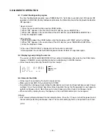
— 32 —
5
-6. Operation of each test
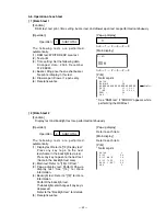
[ 1 ] Batch test 1
[Function]
RAM test, test print, time setting, buzzer test and drawer open test are performed continuously.
[Operation]
Operation :
1
SUBTOTAL
[Print]
* Normal print
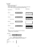
[ 2 ] Batch test 2
[Function]
Display test and backlight test are performed continuously.
The following tests are performed
automatically.
(1) RAM test: WRITE/READ area test.
(2) Test print
(3) Time setting: Set the following data.
Arranged data: 2005 December
31,23:59’30
(4) Buzzer: Ring once the one shot buzzer.
No print or display in this test.
(5) Drawer open: Drawer 1 opens only.
(6) Receipt issuance
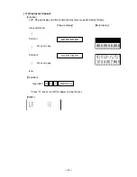
[Pop-up display]
D I A G
1
0 0 n
n
n=0
1
2
3
2
3
[Main display]
n=0
1
2
3
2
3
B A T C H
1
R A M W R
O K
B B B B B B B B B B B B B B B B B B B B B B B B
D A T E
0 5 / 1 2 / 3 1
T I M E
2 3 : 5 9 - 3 0
D R W
1
O K
E N D
1
Print Test
* See “RAM test” if “ERROR” appears while
performing the RAM test.
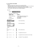
[Operation]
Operation :
2
SUBTOTAL
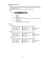
The following tests are performed
automatically.
(1) Display test: Refer to “[12] Display test.”
Press any key to go to the next
test.(Same in the backlight test also)
Press any key to go on to the next test.
(Same in the backlight test also)
(2) Main test: Refer to “[15] LCD test.”
(3) Pop-up display test: Perform Pop-up
display test. See “[14]” for more
information.
(4) Backlight test: Refer to “[13]” for more
information.
Perform the backlight test.
The backlight color changes if any key is
depressed.
Refer to the “Backlight test” for details.
(5) Receipt issuance
[Print]
* Normal print
[Pop-up display]
Refer to each item.
[Main display]
Refer to each item.
B A T C H
2
D I S P
O K
D I S P
M A I N
O K
D I S P
7 S E G
O K
B A C K
L I G H T
O K
E N D
2
Содержание TE-2200
Страница 16: ... 14 DRAWER 35 Remove the case 36 Remove 10 screws 37 Remove the DARWER cable ...
Страница 17: ... 15 38 Remove the Bottom plate 39 Loosen 4 screws 40 Remove the screw and then fix the drawer case ...
Страница 22: ... 20 4 5 DRAWER I F CIRCUIT The drawer open circuit is as follows ...
Страница 23: ... 21 4 6 PRINTER CONTROL CIRCUIT The printer control circuit is as follows ...
Страница 68: ... 66 8 PCB LAYOUT MAIN PCB E466 1 PCB TOP VIEW ...
Страница 69: ... 67 MAIN PCB E466 1 PCB BOTTOM VIEW ...
Страница 83: ... 81 E443 E4 Model Name Board No Drawing No KEY SEET STROKE RJE501624D307 CASIO COMPUTER CO LTD TE 2200 EX 443 ...
Страница 84: ... 82 E544 E4 Model Name Board No Drawing No KEY SEET FLAT RJE501624D315 CASIO COMPUTER CO LTD TE 2400 EX 544 ...
Страница 87: ... 85 TE 2200 KEYBOARD BLOCK 0 00 2 3 4 5 6 7 8 9 1 15 17 16 42 41 18 29 31 30 32 33 35 36 37 38 39 34 40 ...
Страница 93: ... 91 TE 2400 KEYBOARD BLOCK 16 15 17 18 19 20 21 22 23 ...
Страница 98: ... 96 11 DRAWER DL 2429 for USA 16 17 18 11 8 6 15 14 19 9 10 1 12 20 21 5 4 2 3 5 13 7 ...
Страница 100: ... 98 12 DRAWER DL 2797 for Other country 7 12 16 11 8 7 6 9 10 1 20 21 5 4 2 5 17 18 19 18 13 15 14 3 ...
Страница 102: ... 100 13 DRAWER DL 2798 for Europe 7 12 16 11 8 7 6 9 10 1 20 21 5 4 2 5 17 18 19 18 13 15 14 3 ...
Страница 104: ... 102 14 DRAWER DL 2799 for UK Canada 12 17 11 8 7 6 9 10 1 18 19 5 4 2 5 16 13 15 14 3 ...

