2-9
Catalyst 3750-E and Catalyst 3560-E Switch Hardware Installation Guide
OL-9774-04
Chapter 2 Switch Installation
Stack Cabling Configurations
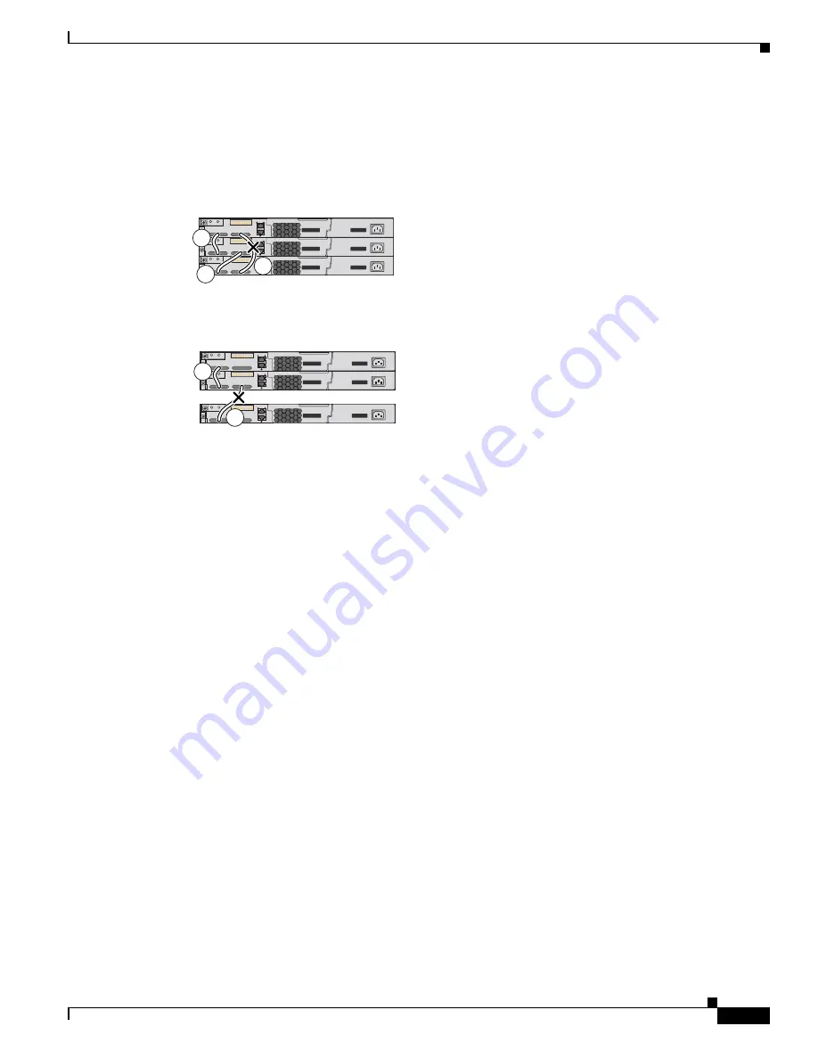
Figure 2-7
and
Figure 2-8
show examples of stacks of Catalyst 3750-E switches with failover conditions.
In
Figure 2-7
, the StackWise cable is bad in link B; therefore, this stack provides only half bandwidth
and does not have redundant connections. In
Figure 2-8
, link B is bad; therefore, this stack partitions into
two stacks, and switch 1 and switch 3 are stack masters.
Figure 2-7
Example of a Stack with a Failover Condition
Figure 2-8
Example of a Partitioned Stack with a Failover Condition
Power On Sequence for Switch Stacks
Consider these guidelines before you power on the switches in a stack:
•
The sequence in which the switches are first powered on might affect the switch that becomes the
stack master.
•
If you want a particular switch to become the stack master, power on that switch first. This switch
becomes the stack master and remains the stack master until a master re-election is required. After
1 minute, power on the other switches in the stack.
•
If you have no preference as to which switch becomes the stack master, power on all the switches in
the stack within a 1-minute timeframe. These switches participate in the stack master election.
Switches powered on after the 1-minute timeframe do not participate in the election.
•
Power off a switch before you add it to or remove it from an existing switch stack.
For conditions that can cause a stack master re-election or to manually elect the stack master, see the
“Managing Switch Stacks” chapter in the switch software configuration guide on Cisco.com.
158110
A
B
C
158111
A
B


