9
alternative to using an external condensate pan, some localities
may allow the use of a separate 3/4--in (19 mm) condensate line
(with appropriate trap) to a place where the condensate will be
noticeable. The owner of the structure must be informed that when
condensate flows from the secondary drain or external condensate
pan, the unit requires servicing or water damage will occur.
Install traps in the condensate lines as close to the coil as possible.
(See Fig. 18.) Make sure that the outlet of each trap is below its
connection to the condensate pan to prevent condensate from
overflowing the drain pan. Prime all traps, test for leaks, and
insulate traps if located above a living area.
Condensate drain lines should be pitched downward at a minimum
slope of 1--in (25 mm) for every 10--ft (3 m) of length.
Consult local codes for additional restrictions or precautions.
Step 8 — Accessories
A. Electric Heaters
See unit rating plate for factory--approved electric heater kits.
Follow installation instructions provided with kit.
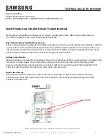
B. Humidifier
Connect humidifier and humidistat to fan coil unit as shown in Fig.
20 and Fig. 21. The cooling lockout relay is optional.
R
G
C
E
L
O
Y
THERMOSTAT
R
R
C
O
Y
G
C
W
2
W
2
W
2
W
3
E
FAN COIL
(CONTROL)
HEAT PUMP
(CONTROL)
RED
GRY
BRN
WHT
WHT
BLU
VIO
HUMIDISTAT
RELAY
FAN HUMIDIFIER
115V
M
A95294
Fig. 20 -- Wiring Layout of Humidifier to Heat Pump
R
G
W
Y
THERMOSTAT
R
G
W
2
W
3
E
C
FAN COIL
(CONTROL)
C
Y
AIR COND.
HUMIDISTAT
FAN HUMIDIFIER
115V
RED
GRY
WHT
WHT
BLU
VIO
BRN
M
A95295
Fig. 21 -- Wiring Layout of Humidifier to Fan Coil
With Electric Heat
Step 9 — Sequence of Operation
A. Continuous Fan
Thermostat closes R to G. G energizes fan relay on PCB which
completes circuit to indoor blower motor. When G is de--energized,
there is a 90 second delay before relay opens.
NOTE
: Speed taps 1, 2 and 3 have a 90 second blower off delay.
Speed taps 4 and 5 have 0 second blower off delay.
B. Cooling Mode
Thermostat energizes R to G, R to Y, and R to O (heat pump only).
G energizes fan relay on PCB which completes circuit to indoor
blower motor. When G is de--energized, there is a 90 second delay
before fan relay opens.
NOTE
: Speed taps 1, 2 and 3 have a 90 second blower off delay.
Speed taps 4 and 5 have 0 second blower off delay.
C. Heat Pump Heating with Auxiliary Electric Heat
Thermostat energizes R to G, R to Y, and R to W. G energizes fan
relay on PCB which completes circuit to indoor blower motor. W
energizes electric heat relay(s) which completes circuit to heater
element(s). When W is de--energized, electric heat relay(s) open,
turning off heater elements. When G is de--energized there is a 90
second delay before fan relay opens.
NOTE
: Speed taps 1, 2 and 3 have a 90 second blower off delay.
Speed taps 4 and 5 have 0 second blower off delay.
D. Electric Heat or Emergency Heat Mode
Thermostat closes R to W. W energizes electric heat relay(s) which
completes circuit to heater element(s). Blower motor is energized
through normally closed contacts on fan relay. When W is
de--energized, electric heat relay(s) opens.
START--UP PROCEDURES
Refer to outdoor unit Installation Instructions for system start--up
instructions and refrigerant charging method details.
UNIT COMPONENT HAZARD
Failure to follow this caution may result in product damage.
Never operate unit without a filter. Damage to blower motor
or coil may result. Factory authorized filter kits must be used
when locating the filter inside the unit. For those applications
where access to an internal filter is impractical, a
field--supplied filter must be installed in the return duct
system.
CAUTION
!
CARE AND MAINTENANCE
To continue high performance and minimize possible equipment
failure, it is essential that periodic maintenance be performed on
this equipment. Consult your local dealer as to the proper
frequency of maintenance contract.
The ability to properly perform maintenance on this equipment
requires certain mechanical skills and tools. If you do not possess
these, contact your dealer for maintenance. The only consumer
service recommended or required is filter replacement or cleaning
on a monthly basis.
PF4M
NB