In Canada, the input rating must be derated by 10 percent for altitudes of 2000 ft to 4500 ft above sea level.
a. Obtain yearly heat value average (at installed altitude) for local gas supply.
b. Obtain yearly specific gravity average for local gas supply.
c. Verify furnace model and select appropriate table. Table 2 can only be used for upflow and upflow/horizontal, 2-speed and
variable-speed, non-condensing furnaces. Table 3 can only be used for downflow and downflow/horizontal, 2-speed, non-condensing
furnaces.
d. Find installation altitude in Table 2 (for upflow and upflow/horizontal models) or Table 3 (for downflow and downflow/horizontal
models).
NOTE:
For Canada altitudes of 2000 to 4500 ft, use U.S.A. altitudes of 2001 to 3000 ft in Table 2 or 3.
e. Find closest natural gas heat value and specific gravity in Table 2 (for upflow and upflow/horizontal models) or Table 3 (for downflow
and downflow/horizontal models).
f. Follow heat value line and specific gravity line to point of intersection to find orifice size and manifold pressure settings for proper
operation at given natural gas condition.
EXAMPLE: (Using Table 2 at 0—2000 ft altitude)
Heat value 1050 Btu/cu ft
Specific gravity 0.62
Therefore, Orifice No. 45 is required.
8. Install main burner orifices. Finger-tighten orifices at least 1 full turn to prevent cross threading, then tighten with wrench. There are enough
orifices in each kit for the largest furnace. Discard extra orifices. Orifices of other sizes must be field supplied and are available through
your local distributor.
NOTE:
DO NOT reinstall main burners or burner hold-down bracket at this time.
PROCEDURE 2—REPLACE AND CONVERT GAS VALVE. (SEE FIG. 4.)
NOTE:
Discard labels and instructions packaged with White-Rodgers gas valve. All necessary information is provided in this instruction.
1. Be sure gas and electrical supplies to furnace are off.
2. Remove wires from gas valve. Note location for reassembly.
3. If a low gas pressure switch (LGPS) is installed on inlet pressure tap of gas valve, remove 2 wires to LGPS.
CAUTION: Label all wires prior to disconnection when servicing controls. Wiring errors can cause improper and
dangerous operation.
ATTENTION:
Lors des opérations d’entretien des commandes, étiqueter tous les fils avant de les déconnecter. Toute
erreur de câblage peut être une source de danger et de panne.
4. Remove gas supply line from gas valve.
5. Remove propane gas valve using backup wrench and discard valve. On some models, the pressure switch assembly may need to be loosened
and moved aside to permit removal of the gas valve.
NOTE:
Propane gas valve has RED knob, and natural gas valve has a BLUE knob or ELECTRIC SWITCH.
6. Modify natural gas valve.
a. Remove burner enclosure reference pressure tap from natural gas valve. (See Fig. 4.)
b. Remove plug button from same location on propane gas valve and insert in hole in new natural gas valve from which pressure tap was
removed.
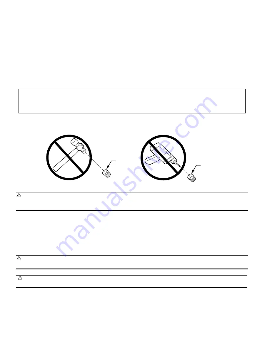
CAUTION: DO NOT redrill burner orifices. Improper drilling (burrs, out-of-round holes, etc.) can cause excessive
burner noise and misdirection of burner flames. This can result in flame impingement of the burners and heat exchanger
causing failure. Obtain new orifices if orifice size must be changed.
A96249
BURNER
ORIFICE
BURNER
ORIFICE
—4—
→


