Nov-21
Page 62 of 132
59812-K001 Rev 10
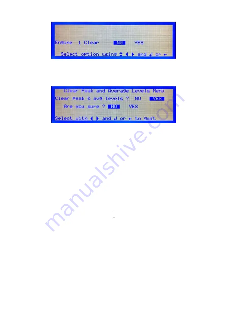
Figure 72
Clear Max Average Levels
c.
Select Yes to confirm the levels are to be cleared.
d.
From the Configuration menu, Figure 42, select 8. Clr Peak & Avg
Figure 73
Clear Peak and Average Levels
e.
Select Yes to confirm the levels are to be cleared.
8.
To release the pipe from the connector, press in the metal collar on the end of the connector
at the same time as pulling the pipe out
9.
Remove the nylon pipe from the pipe connector for stowage purposes.
10.
The wick is reusable and can be left in the wick holder. Fully extinguish the wick after use
at all times.
11.
Refer to the Material Safety Data Sheet in the event of health or safety issues.
Method 2 - Using Artificial Smoke
It is important when using this method that only approved smoke canisters are used as other brands
may deposit residue within the detector sample chamber affecting the performance.
Smoke canisters approved for use on the Graviner Mk7 Oil Mist Detection system are:
HSI Fire and Safety SmokeCheck 25S
HIS Fire and Safety PurCheck
When using this type of spray canister, it will inject smoke at a rate where the rise of oil mist is rapid and
will pass through the alarm thresholds extremely quickly.
1.
Push the nylon pipe of the smoke tester into the connector on the side of the detector base body
(refer to Figure 70).
2.
Using a can of artificial smoke, spray enough artificial smoke into the pipe connector to cause
an alarm condition.
3.
After tests are completed the maximum actual average level, Detector peak level and current
average readings should be erased.
Содержание Graviner Mk6
Страница 16: ...Nov 21 Page 16 of 132 59812 K001 Rev 10 Height 309mm Width 559mm Depth 118 5mm Weight 8 7kg ...
Страница 26: ...Nov 21 Page 26 of 132 59812 K001 Rev 10 Figure 9 Junction Box Installation ...
Страница 29: ...Nov 21 Page 29 of 132 59812 K001 Rev 10 Figure 12 Detector Head Installation ...
Страница 30: ...Nov 21 Page 30 of 132 59812 K001 Rev 10 Figure 13 Detector Head Installation Short Sample Pipe ...
Страница 46: ...Nov 21 Page 46 of 132 59812 K001 Rev 10 Figure 36 System Drawing ...
Страница 47: ...Nov 21 Page 47 of 132 59812 K001 Rev 10 Figure 37 Wiring Diagram ...
Страница 112: ...Nov 21 Page 112 of 132 59812 K001 Rev 10 6 6 1 CONTROL PANEL Figure 158 Control Panel Door ...
Страница 123: ...Nov 21 Page 123 of 132 59812 K001 Rev 10 ...
Страница 126: ...Nov 21 Page 126 of 132 59812 K001 Rev 10 ...
Страница 129: ...Nov 21 Page 129 of 132 59812 K001 Rev 10 ...


