


5
NOTE
: Condensate trap is to be built in the field per Fig. 7.
Wood frame or blocks may be used to raise the boiler
to maintain drain pitch or to be above external condensate
pump reservoir.
There is a 115 volt AC receptacle provided on the service switch
junction box located at the boiler right side, to provide power for
an external condensate pump (if needed).
FOUNDATION REQUIREMENTS
Boiler must be placed on level surface. Boiler is NOT to be
installed on carpeting.
NOTE
: If boiler is not level, condensate drain lines will not
function properly. Adjustable feet are located on the boiler to
make up for minor surface irregularities or tilt.
Wood frame or blocks may be used to raise boiler to maintain
drain pitch or to be above external condensate pump reservoir.
REMOVAL OF EXISTING BOILER FROM COMMON
VENT SYSTEM
When an existing boiler is removed from a common venting
system, the common venting system is likely to be too large for
proper venting of the appliances remaining connected to it.
CARBON MONOXIDE POISONING HAZARD
Failure to follow the steps oulined below for each
appliance connected to the venting system being placed
into operation could result in carbon monoxide
poisoning or death.
At the time of removal of an existing boiler, the
following steps shall be followed with each appliance
remaining connected to the common venting system
placed in operation, while the other appliances
remaining connected to the common venting system are
not in operation.
!
WARNING
1. Seal any unused openings in the common venting system.
2. Visually inspect the venting system for proper size and
horizontal pitch as required in the National Fuel Gas Code,
ANSI Z223.1--2002/NFPA 54--2002 or the CSA B149.1,
Natural Gas and Propane Installation Code and these
instructions. Determine there is no blockage or restrictions,
leakage, corrosion and other deficiencies which could
cause an unsafe condition.
3. When it is practical, close all building doors and windows
and all doors between the space in which the appliances
remaining connected to the common venting system are
located and other spaces of the building.
4. Close fireplace dampers.
5. Turn on clothes dryer and any appliance not connected to
the common venting system. Turn on any exhaust fans,
such as range hoods and bathroom exhaust, so they will
operate at maximum speed. Do not operate a summer
exhaust fan.
6. Place in operation the appliance being inspected. Follow
the lighting instructions. Adjust thermostat so appliances
will operate continuously.
7. Test for spillage at the draft hood relief opening after 5
minutes of main burner operation. Use the flame of a
match or candle, or the smoke a cigarette, cigar or pipe.
8. Any improper operation of the common venting system
should be corrected so the installation conforms with the
National Fuel Code, ANSI Z223.1--2002/NFPA 54--2002
and/or CSA--B149.1, Natural Gas and Propane Installation
Code for Canadian standards.
9. After it has been determined that each appliance remaining
connected to the common venting system properly vents
when tested as outlined above, return doors, windows,
exhaust fans and any other gas--burning appliances to their
previous condition of use.
STEP 3
—
Placing the Boiler
The boiler should be placed to provide the most direct
connections to the combustion air, vent and system piping as
possible.
Place crated boiler as close to selected location as possible and
uncrate boiler. The uncrated boiler may be moved into position
with an appliance dolly or 2--wheel hand truck. The dolly or hand
truck should be inserted under the
right hand side
of the boiler.
It is possible to slide the boiler for a short distance on a smooth
floor or surface.
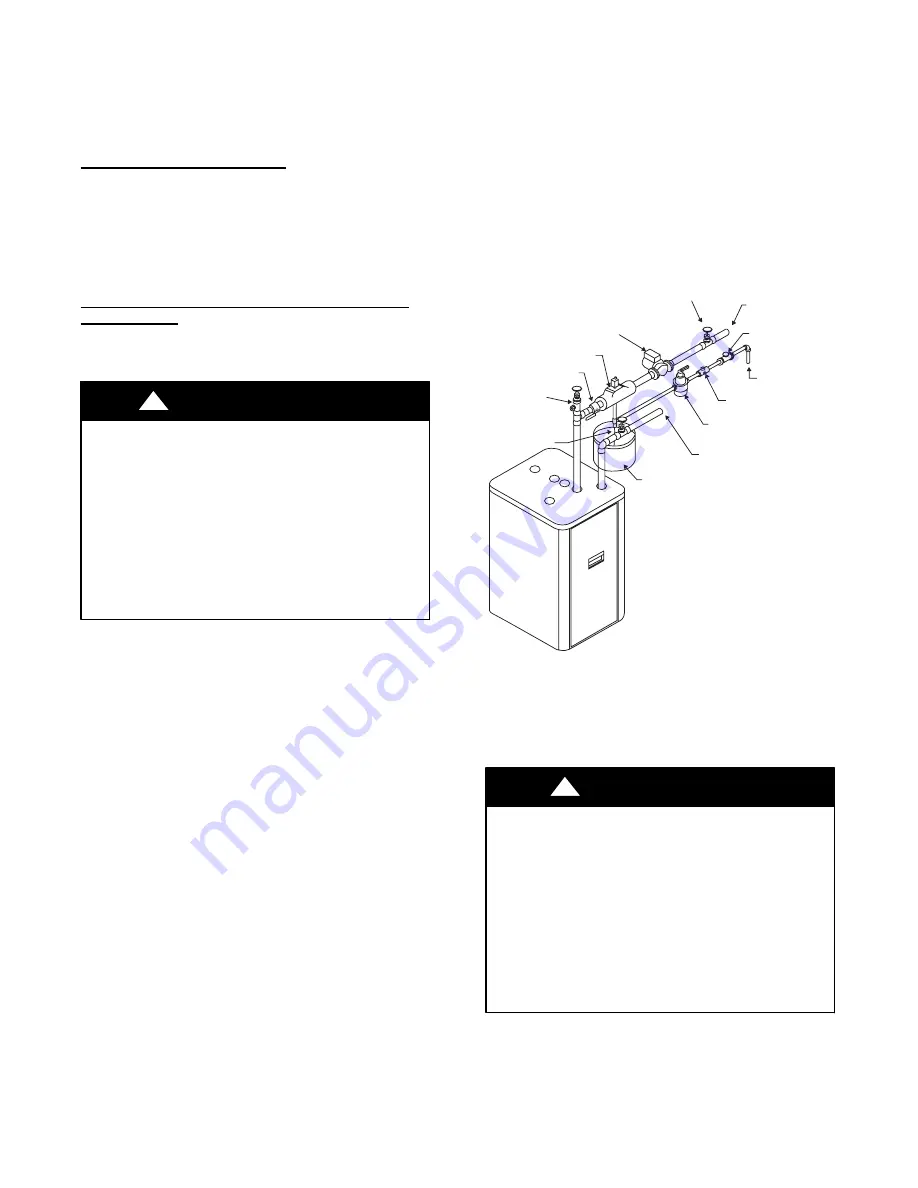
EXPANSION TANK
RETURN FROM
SYSTEM
PRESSURE
REDUCING VALVE
REDUCED PRESSURE
BACKFLOW PREVENTER
FEED
WATER
GATE VALVE
SUPPLY TO
SYSTEM
SERVICE
VALVE
CIRCULATOR
CAN VENT
SHUT OFF VALVE
PURGE VALVE
SERVICE
VALVE
A04050
Fig. 2
---
Single Zone Boiler Piping
NOTE
: Refer to manual section “LOCATING THE BOILER”
for required clearances for servicing and maintenance.
STEP 4
—
Near Boiler Piping
UNIT CORROSION HAZARD
Failure to follow this caution may result in property or unit
damage.
Copper supply and return piping must NOT be installed
directly into aluminum boiler section castings due to
galvanic corrosion between dissimilar metals. Iron or steel
bushings or pipe nipples should be used between copper
system piping and boiler to make final connection to boiler.
Also, the use of dielectric unions is acceptable. The
packaged boiler is furnished with iron piping in the front
boiler section for the supply and return connections.
CAUTION
!
When the installation of the boiler is for a new heating system,
first install all of the radiation units (panels, radiators, baseboard,
or tubing) and the supply and return mains. After all heating
system piping and components have been installed, make final
connection of the system piping to the boiler.


