Carrier 40VM Series Скачать руководство пользователя страница 9

9

Locking function

The wired controller can lock the following functions. They


cannot be changed using the icons on the wired controller. 

Choosing “Lock” on the “Menu” interface will lock:

• The IDU power-on/off function

• Running mode

• Temperature setting

• Schedule setting

1.

Choose “Touch tone” on the menu interface.

2.

Turn Touch tone ON/OFF.

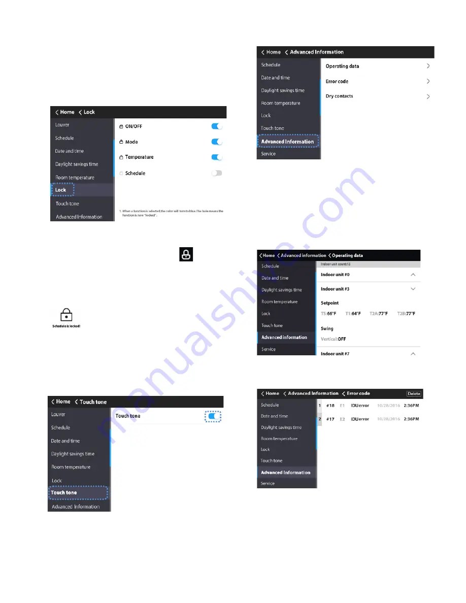
Advanced information — 

Choose “Advanced

Information” on the Menu interface.

Querying indoor unit operating data — 

1.

Choose “Operating data” on the “Advanced Information”
interface.

On the “Operating data” interface, the wired controller will


display indoor unit address.

2.

Touch the indoor unit # icon.

The  wired  controller  will  display  the  number  of  indoor  units


connected to the wired controller, indoor units' temperature


sensor readings, and louver settings.

Querying error records  — 

Choose “Error code”


on

the “Advanced Information” interface.

• The wired controller saves up to 20 groups of fault

records.

• Touch the Delete icon to delete all the error messages.

• It displays the unit address (0~63 for indoor unit and 128

for outdoor unit) and the related error code.

• An address is not displayed when the wired controller

has a fault.

Fig. 33 —Query Error Records

Fig. 31 —Advanced Information

Fig. 32 —Query IDU Operating Data

Fig. 29 —Locking Function

When a function is selected, the color will turn to blue


meaning that the function is now “locked”.
When  the  locking  function  is  enabled,  the 

  icon  will  be


displayed on the homepage. When the locked function icon is


selected, it will blink indicating that the function is locked.
When  the  schedule  setting  is  locked,  the  system  prompts  the


user that the weekly schedule is locked when you try to access


the week timing mode.

Note:

 If the central controller is sending locking signals


to 

an IDU while the touch screen wired controller also sends


command  to  the  same  IDU  simultaneously,  the  locking


command from the central controller may be invalid.

Setting the touch tone  — 

Fig. 30 —Touch Tone

When a corresponding option is turned on, a beep is 
generated when the button is touched.

Содержание 40VM Series

Страница 1: ...sult in severe personal injury or death WARNING signifies hazards that could result in personal injury or death CAUTION is used to identify unsafe practices Table 2 Wired Controller Accessory Usage NA...

Страница 2: ...he central controller locks the IDU function and the wired controller cannot use the corresponding functions of the IDU 16 Schedule Turns on when the weekly schedule is available on the wired controll...

Страница 3: ...3 DIMENSIONAL DRAWING 7 1 4 4 7 8 1 1 8 Front View Side View Rear View 2 1 4 3 1 8 Fig 2 Dimensions Note All dimensions are shown in inches...

Страница 4: ...indoor units see Fig 4 2 Connect field provided 24VAC power to R and C terminals 1 Remove back cover from controller as shown in Figure 5 2 Cut a hole in the wall for the 2 wire bundles Run the wires...

Страница 5: ...is turned on as shown in Figure 10 Touch the corresponding fan speed text or the icon to set the fan speed See Figure 12 Fig 8 Snap controller into place Push WALL Fig 9 Turn screen on Fig 10 On Off s...

Страница 6: ...E AND TIME Used to configure date and time settings and corrections DAYLIGHT SAVINGS TIME Used to adjust the clock in observance of daylight savings time ROOM TEMP Used to set display room temperature...

Страница 7: ...Reset to reset all the scheduled tasks Holiday settings 1 Touch the icon from the Setting Schedule screen Figure 20 to access Holiday settings Touch to create a new Holiday Touch Edit to adjust the ex...

Страница 8: ...ose Daylight savings time on the Menu interface 2 Turn the Daylight savings time ON OFF 3 Touch the Edit icon 4 Slide the corresponding items to set the start date and end date respectively 5 Touch th...

Страница 9: ...rds Touch the Delete icon to delete all the error messages It displays the unit address 0 63 for indoor unit and 128 for outdoor unit and the related error code An address is not displayed when the wi...

Страница 10: ...tion setting on the Service interface Fig 35 Query Dry Contact Status Fig 36 Service Menu Password Entry Fig 37 Room temp location The room temperature location can be set to Indoor unit or Wired remo...

Страница 11: ...below this setting Default setting is 68F Fig 43 Thermo Off Fan Speed This determines IDU fan behavior when the zone is satisfied thermo off for both heating and cooling mode For cooling mode the defa...

Страница 12: ...tal Heat Aux Heat Status These settings are used when the IDU is controlling a field provided auxiliary heat source via its ACB interface contact output Turning Aux Heat Status on enables this functio...

Страница 13: ...hedules room temperature display etc Reset setting 1 Choose Reset setting on the Service interface 2 Touch the Reset icon to reset 3 Touch the YES icon to confirm the operation Fig 52 Firmware Update...

Страница 14: ...tic pressure of the DC fan 0 0 in WC default 1 0 04 in WC 2 0 08 in WC 3 0 12 in WC 4 0 16 in WC 5 0 20 in WC 6 0 24 in WC 7 0 28 in WC 8 0 32 in WC 9 0 36 in WC 10 0 40 in WC 11 0 44 in WC 12 0 48 in...

Отзывы: