12
30RB
6OJUDJSDVJUEJBHSBN
'JH
5IJTDIFDLCFDPNFTOFDFTTBSZBGUFSBOZSFGSJHFSBOUMFBLPS
after replacement of the compressor.
The best method to correctly charge refrigerant is to
completely empty the refrigerant circuit using refrigerant
recovery equipment.
Then charge the exact quantity of refrigerant according to
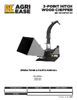
Legend - Fig. 17
1. High pressure transducer
2. High pressure switch (when installed)
3. Low pressure transducer
1SFTTVSFTFSWJDFQPSU
5.
TEV
valve
$SBOLDBTFIFBUFS
7.
Suction
accumulator
8.
Water
inlet
9. Chilled water outlet
Refrigerant R-410A
Gas
-JRVJE(BT
Liquid
the data shown on the unit nameplate.
R-410A systems must be charged with liquid refrigerant.
Use the special recharging equipment (normally on the
NBSLFUUPDPOUSPMUIFSFGSJHFSBOUDPSSFDUMZ
3FNPWFVOJUUPQDPWFSCZMPPTFOJOHUIFöYJOHTDSFXTBOE
lifting the cover. Carefully clean the coil with a vacuum
cleaner from inside to outside. With the same vacuum
cleaner, remove the dust from inside the fan compartment
and the fan blades. Avoid any damage to the blades which
may cause future vibrations and noise.
Replace the unit cover and tighten the screws.
If necessary, proceed as follows for
more careful cleaning of the coil:
Switch the mains supply OFF.
IMPORTANT
The operation must be performed by
RVBMJöFEQFSTPOOFM
Cleaning the coil
3FGSJHFSBOUDIBSHFDIFDL
Maintenance
$POUSPMBOETBGFUZEFWJDFT
$PNQSFTTPSBOEGBONPUPSXJOEJOHQSPUFDUJPO
Automatic
reset.
This is activated when the temperature of the winding or
the the compressor power input exceed the set limits.
'SFF[FVQQSPUFDUJPO
5IJTQSPUFDUJPOEFWJDFJTDPOUSPMMFECZUIF1SP%JBMPH
+VOJPSDPOUSPMVTJOHUIFXBUFSIFBUFYDIBOHFSMFBWJOH
temperature.
This safety device interrupts unit operation and shows
an alarm code on the display.
$PPMJOHDPOUSPMTFUQPJOU
This parameter is regulated by the control and
factory set to an leaving water temperature of 7°C.
The second set point default value is 12°C and it can be
selected via the Service Interface.
)JHIQSFTTVSFTXJUDI)*1
Installed and set according to technical data table
on the discharge piping with manual reset. On unit
XJUIPVU)*1IJHIQSFTTVSFQSPUFDUJPOJTBTTVSFECZ
compressor overload switch.
-PXTVDUJPOUFNQFSBUVSFQSPUFDUJPO
Automatic/manual reset (after 6 automatic cycles)
based on the pressure transducer signal installed on the
compressor suction lines.
)JHIQSFTTVSFQSPUFDUJPO
Automatic/manual reset (after 6 automatic cycles)
based on the pressure transducer signal installed on the
compressor discharge lines.
'BOTQFFEDPOUSPMMFS
Changes the fan speed according to the condensing
UFNQFSBUVSF*TDPOUSPMMFECZUIF1SP%JBMPHDPOUSPM
BOEQFSNJUTVOJUPQFSBUJPOVQUPUIFTQFDJöFE
temperature limits, optimising the condensing
temperature.
t
Anti-short-cycle protection.
t
Fault detector for the temperature and pressure
sensors.
English
Содержание 30RB008-9
Страница 1: ...Air Cooled liquid chillers 30RB InstallationManual P R O D I A L O G...
Страница 3: ...III 30RB 600 150 150 400 363 6 5 4 7 A B...
Страница 5: ...V 30RB 11 1 2 3 3 3 8 4 6 1 5 7 9 12 1 1 2 3 3 4 6 5 7...
Страница 7: ...VII 30RB A C D B A C D B 15 A B...
Страница 9: ...IX 30RB 18 19 17...