


17
MAINTENANCE
Periodic maintenance is necessary to keep all components
functioning as designed. A maintenance log is recommended
to ensure a proper maintenance schedule is followed.
Pumpout Compressor Oil Charge —
Use oil con-
forming to Carrier specifications for centrifugal or screw com-
pressor use. Oil requirements are listed in Table 6.
Monitor and adjust compressor oil level as often as
necessary. When replacing lost oil, add the same type of oil that
is used in the chiller being pumped out.
Table 6 — Pumpout Compressor Requirements
The pumpout oil separator comes pre-charged with 13 oz of
ISO viscosity 220 POE (Polyol Ester) oil. The pumpout com-
pressor is approved for use with ISO viscosity 220 POE oil or
ISO viscosity 68 POE oil. The pumpout compressor is also fac-
tory precharged with POE oil.
Oil should be visible in the pumpout compressor sight glass
both during operation and at shutdown. Always check the oil
level before operating the pumpout compressor.
Oil can be added to the 1/4-in. SAE flare access valve port
running from the top of the oil separator to the compressor
while the compressor is running. Be careful not to overfill.
NOTE: Compressor access valve has a self-sealing fitting
which will require a hose connection with a depressor to open.
To change or remove oil, the compressor will have to be re-
moved from the assembly. Compressor can be disconnected
from connected tubing by the quick connect fittings at suction
and discharge and oil recovery line.
Prior to removal, close service valves 2, 3, 4, and 5, and run
the pumpout compressor in AUTOMATIC until the vacuum
switch is satisfied and the compressor shuts off.
Move pumpout selector switch to OFF, and turn off all power
to unit prior to removing compressor unit from pumpout as-
sembly frame and connecting tubing.
Service valves 2, 3, 4, and 5 remain closed while compres-
sor is removed. Put compressor back in place. Use the torque
values listed in Table 7 for reassembly:
Table 7 — Torque Values for Reassembly
Be sure to use backup wrench and pull a deep vacuum in the
serviced pumpout tubing prior to any refrigerant exposure. At
this point, confirm that the oil level is satisfactory and put the
pumpout back in service.
Storage Tank —
To prevent moisture and contaminants
from entering the storage tank, maintain positive pressure in
the tank when not transferring refrigerant. Leak test the storage
tank periodically.
Ordering Replacement Parts —
The following in-
formation must accompany an order for Carrier-specified parts:
• machine model number and serial number
• name, quantity, and part number of the part required
• delivery address and method of shipment
TROUBLESHOOTING
Information on troubleshooting for the PPS system is in-
cluded in Table
8.
a19-2435
7
1a
11
8
1b
5
3
4
2
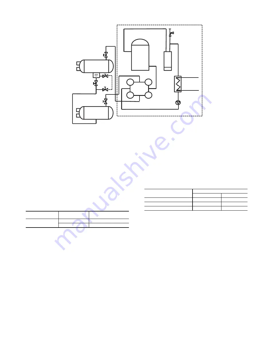
PUMPOUT
COMPRESSOR
OIL
SEPARATOR
RELIEF
VALVE
PUMPOUT
CONDENSER
CHECK
VALVE
CONDENSER
COOLER
Fig. 11 — Typical Optional Pumpout System Piping Schematic without Storage Tank
NOTE: Valve 8 is only applicable for products with linear float valves.
REFRIGERANT
ISO
VISCOSITY
CARRIER
SPECIFICATION NO.
R-134a
68
PP47-31
220
PP47-32
PARAMETER
VALUES
ft-lb
Nm
Suction
80 to 100
109 to 136
Discharge
50 to 60
68 to 81
O-ring Face Seal
7 to 9
10 to 12
Содержание 19XR Series
Страница 19: ......


