


7. Auxiliary evacuation pump, 5 cfm (2.5 l/s) or greater,
with oil trap, flexible connecting hose and connection
fittings
8. Compound pressure gage, 30-in. vacuum to 30 psig (75
cm vacuum to 200 kPa)
9. Digital volt-ohmmeter and clamp-on ammeter
10. Liquid charging hose consisting of flexible
3
⁄
4
-in.
(20- mm) hose connected to a 3-ft (1-m) long x
1
⁄
2
-in.
(15-mm) pipe trimmed at a 45-degree angle at one end,
with a
1
⁄
2
-in. MPT connector
11. Leak detector
12. Hydrometer and insertion thermometer
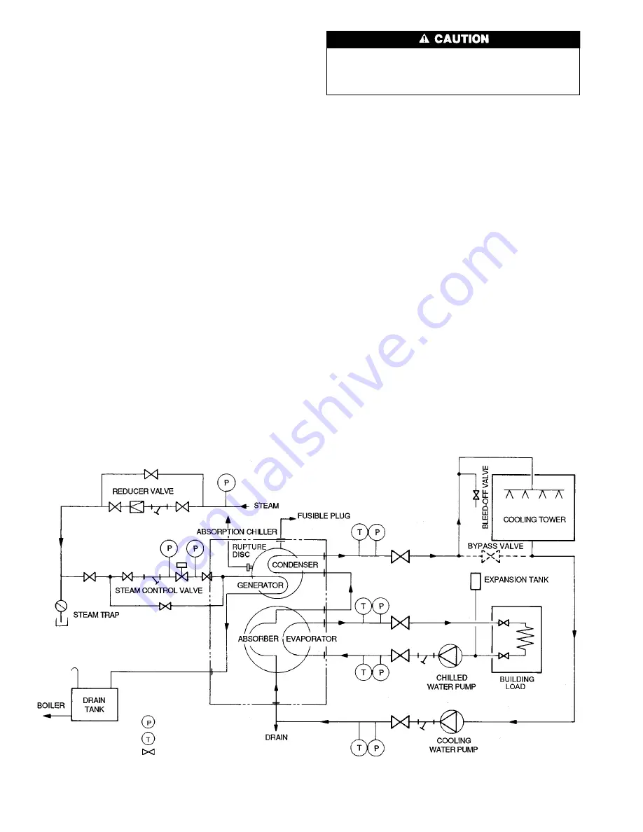
Inspect Field Piping —
Refer to the field piping dia-
grams (Fig. 19) and inspect the chilled water and cooling
water piping.
1. Verify that location and flow direction of the water lines
are as specified on the drawings and as marked on the
machine.
2. Check that all water lines are vented and properly sup-
ported to prevent stress on waterbox covers or nozzles.
3. Make sure all waterbox drains are installed.
4. Ensure that water flow through the evaporator and con-
denser meet job requirements. Measure the pressure drops
across both cooler and condenser.
5. Make sure chilled water temperature sensors are installed
in the leaving chilled water piping. Also check that ap-
propriate thermometers or temperature wells and pres-
sure gage taps have been installed in both entering and
leaving sides of the evaporator, absorber, and condenser
water piping.
Inspect Field Wiring —
Refer to the field and ma-
chine wiring diagrams and inspect the wiring for both power
supply and connections to other system equipment (cooling
tower, water supply pumps, auto. start if used, etc.)
Do not apply power to hermetic pumps or attempt to
start the machine until it has been charged with lithium
bromide solution and refrigerant. The pumps will be se-
verely damaged if rotated without the full liquid charge.
1. Examine wiring for conformance to job wiring diagrams
and applicable electrical codes.
2. Check pump and motor nameplates and control panel for
agreement with supply voltage and frequency (Hz).
3. Verify correct overload and fuse sizes for all motors.
4. Check that electrical equipment and controls are properly
grounded in accordance with applicable electrical codes.
5. Make sure customer/contractor has verified proper op-
eration of water pumps, cooling tower fan, and associ-
ated auxiliary equipment. This includes ensuring that motors
are properly lubricated and have proper electrical supply
and proper rotation.
Standing Vacuum Test —
Before machine is ener-
gized or placed in operation, check for air leaks with a stand-
ing vacuum test. Examine the 2 test procedures described
below and select the one that applies to your job application.
LONG INTERVAL TEST — Use this test procedure if an
absolute pressure reading has been recorded at least 4 weeks
previously and the reading was not more than 1 in.
(25 mm) of mercury.
1. Connect an absolute pressure gage to the auxiliary evacu-
ation valve and record the pressure reading. (Do not use
mercury gage.)
2. If the pressure has increased by more than 0.1 in.
(2.5 mm) of mercury since the initial reading, an air leak
is indicated. Leak test the machine as described in the
Maintenance Procedures section, page 33, then perform
the short interval test which follows.
Pressure Gage
Thermometer
Manual Valve
Fig. 19 — Typical Piping
20
Содержание 16JT Series
Страница 11: ...Fig 10 Typical Wiring Diagram 11 ...
Страница 12: ...Fig 10 Typical Wiring Diagram cont 12 ...
Страница 13: ...Fig 11 Typical Control Wiring 13 ...
Страница 43: ......


