Carlin 51300S Скачать руководство пользователя страница 6

6

7


SEAL THE COVER

•  Install the rubber filler


18


into the 4" opening in the bot-

tom of the cover


1


 as shown.

8


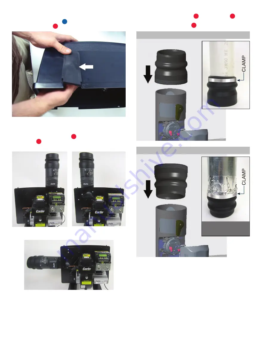
INSTALL THE AIR INLET
•  Using the screws provided


10b


, mount the CAP System  

air inlet


10


onto the 2" x 4" air inlet knockout removed in 

Step 5. Mounting examples below.

9


Slide the connecting flange


11


 onto the air inlet 

10


until fit is tight. Reverse flange when using galvanized  

piping. Secure with clamp


6


.

VERTICAL CONFIGURATIONS

HORIZONTAL CONFIGURATION (left side only)

Galvanized pipe requires 
hi-temp foil tape or mastic 
tape (see Step 12). 

GALVANIZED

PVC

Содержание 51300S

Страница 1: ...hout covers 0 50 2 00 51300AS Low Rate CAP Kit for Carlin burners with covers 0 50 1 00 51300BS Medium Rate CAP Kit for Carlin burners with covers 1 05 1 45 51300CS High Rate CAP Kit for Carlin burner...

Страница 2: ...C A P S Y S T E M K I T C O M P O N E N T S s e e p a g e 3 f o r p a r t d e s c r i p t i o n s 8 13 9 1 14 17 18 20 15 19 16 2 12 3 6 7 4 5 10 11 10a 10b 10c 1b 1a 19a COMPONENTS CONTAINED IN POLYB...

Страница 3: ...ssembled with CAP System Air Inlet above 10a 24 inch Air Flow Switch Wiring Harness 51308A 1 10b 10 14 x 1 2 Phillips Head Screw 50605 2 10c 8 16 x 3 4 Phillips Head Screw 51327 1 11 Connecting Flange...

Страница 4: ...the burner cover backplate 2 5 REMOVE AIR INLET KNOCKOUT Remove the 2 x 4 air inlet knockout that corresponds to the desired air inlet position vertical or horizontal as shown in step 8 Pressure Swit...

Страница 5: ...kplate 2 Secure the filler plate 19 below the burner air tube using the two 5 16 bolts and star washers 14 provided Install the 1 62 split grommet 17 around any BX cable wiring harness etc leaving the...

Страница 6: ...em air inlet 10 onto the 2 x 4 air inlet knockout removed in Step 5 Mounting examples below 9 Slide the connecting flange 11 onto the air inlet 10 until fit is tight Reverse flange when using galvaniz...

Страница 7: ...ng the cover 14 CHECK BURNER SETUP CAP System utilizes outside air for combustion Incoming air temperature will fluctuate by season which can significantly impact combustion Use the table below to set...

Страница 8: ...components in the Burner Seal Kit see Step 6 Make sure that the burner cover screw 1b is tight This also prevents basement air from entering the cover Check that the correct air pressure switch 3 4 5...

Отзывы: