Wiring
Startup & Operation
Do not start the burner if the combustion chamber
contains oil or oil vapor.
Per UL requirements, the control will not turn on if the
CAD cell senses flame during the self-test. If the CAD cell sees light (flame) at the beginning of a cycle, the control will remain in
self-test mode until the CAD cell no longer senses light (flame). The amber LED will blink momentarily every 3 to 4 seconds and
green LED will be on or flashing.
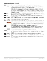
Power ON
Open all manual oil line valves. Close the line switch. (If Red LED turn on constant , control is in lockout.
See below to reset.)
Self-test 1
The control performs a “boot-up” test to verify internal operation each time power is applied to the black
wire. The amber LED turns on and the test continues for about 5 seconds. If the test fails, the control turns
the amber LED off and repeats this test sequence until successful.
Stand-by
(Thermostat circuit open and/or limit circuit open) If Self-test 1 is successful, amber LED turns off and
control waits for thermostat circuit to close and a limit input.
Call for
Set thermostat to call for heat. Thermostat circuit must be closed and black wire must receive
heat
power from the limit circuit.
Self-test 2
If a failure occurs in this self-check, the control won’t start and the amber LED blinks 1 second on, 4 sec-
onds off, until serviced or the problem clears. These failures include CAD cell seeing light, internal failure,
or line voltage <90V. See service section.
© Copyright 2015 - Carlin Combustion Technology, Inc.
MN50200 022415
Bundled Neutrals Can Be Attached to Any L2 T
erminal
Latch-Up:
Pr
events excessive r
esets by locking out after 3
consecutive r
esets during any one call for heat.
To
r
eset fr
om Latch-Up:
1. Depr
ess and hold the r
ed button. Amber light will
blink after 10 seconds, r
ed light will stay on solid.
2. After amber light stops blinking (appr
oximately
20 seconds),
re
lease r
ed button.
Releasing red button during step 1 and 2 will result
in the control returning to latch-up
Model 50200 Diagnostic LEDs
– Amber OFF
– Amber ON
– Amber FLASHING
– Green OFF
– Green ON
– Green FLASHING
– Red OFF
– Red ON
– Red FLASHING


