background image

Model 99FRD, 100CRD & 102CRD oil burners — Instruction manual

Carlin part number MN99102 Rev. 08/20/08

– 12 –

3.  Prepare burner 

(continued)

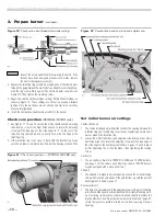
•  The nozzle line heater needs power when the burner is in standby (no 

call for heat from the appliance). Make sure the nozzle line heater is 
powered directly from the 120 VAC HOT line, not through the appliance 
operating control circuit. The nozzle line heater wiring should be shown 
on the wiring diagram supplied with the appliance/burner unit.

•  The nozzle line heater is supplied with an electrical disconnect harness, 

allowing removal of the combustion head assembly without discon-
necting wires. Position the heater harness disconnect in the rear of 
the blower housing, above the blower access cover. The wire leads to 
the disconnect route through the side of the housing into the junction 
box.

  When first starting the burner, or after the service switch has 

been off for some time, the heater requires about 15 minutes 
to bring the oil to operating temperature.

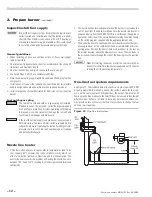
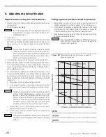
Figure 14

  One-line fuel system

One-line fuel system requirements

See Figure 14. The standard burner fuel unit is a single-stage, 3450-RPM 
oil pump. Apply this fuel unit only on one-line systems where the fuel sup-
ply is on the same level with, or higher than, the burner. This ensures oil 
flow by gravity. Also make sure the total lift does not exceed 8 feet (height 
difference from bottom of oil tank to fuel unit). For other conditions, you 
must provide a two-line fuel system. You may also have to change the fuel 
unit to a two-stage type.

Inspect/install fuel supply

  Inspect the oil supply system. Ensure that the fuel lines are 

correctly sized and installed and that the fuel flow is unob-
structed, the oil tank is clean and only # 1 or # 2 heating oil 
are supplied. Failure to supply a reliable oil flow could result 
in loss of heat and potential severe equipment damage.

Nozzle line heater

•  Oil burners often operate in spaces where temperatures tend to be 

cool, typically 60°F or lower. Cool oil has higher viscosity, which can 
affect  atomization,  ignition,  combustion  and  fuel  consumption. The 
nozzle line heater avoids this problem by heating the nozzle line oil to 
between 120°F and 130°F, resulting in smoother ignition and improved 
combustion.

General guidelines:

•  When installing oil lines, use continuous runs of heavy-wall copper 

tubing if possible.

•  Check fuel unit (oil pump) data sheet for recommended line sizing, lift 

limitations and maximum length.

•  Check all connections and joints to ensure they are air-tight.
•  Use flare fittings. Do NOT use compression fittings.
•  Never use pipe sealing tape. Fragments can break off and plug fuel line 

components.

•  Install a shut-off valve at the tank and one near the burner. (Use fusible 

handle design valves when possible or when required by codes.)

•  Install a large capacity fuel filter (rated for 50 microns or less) near the 

burner.

Fuel unit bypass plug

  The fuel unit is shipped with its  bypass plug not installed, 

intended for a one-line oil system. Install the bypass plug only 
if connecting to a two-line oil system. Operating with the plug 
in place on a one-line system will damage the fuel unit and 
could lead to oil leakage and fire hazard.

  If the fuel line or fuel supply is above burner, never exceed 3 

PSIG pressure at the fuel unit inlet. Install a suitable OSV to 
reduce the pressure. Operating the fuel unit with higher inlet 
pressure could result in fuel unit seal damage, oil leakage 
and potential fire hazard.

Содержание 100CRD

Страница 1: ...y stated other wise this manual must be used only by a qualified service technician Failure to comply with this or other requirements in this manual could result in severe personal injury death or sub...

Страница 2: ...w Train the user To properly operate the burner appliance per this manual and the appliance instructions see User s information To keep this manual at or near the burner appliance for ready ac cess by...

Страница 3: ...ctions when appliance data is not available Table 1 Apply the guidelines below to select a nozzle when appliance specific nozzle data is not avialable from the manufacturer See notes at end of table f...

Страница 4: ...uvers screens Air opening sizes are always given in free area This means after deduction for louver obstruction If you can t find the louver reduction for the grilles used assume free area is 20 of to...

Страница 5: ...ponents maintain all necessary clearances to combustible construction including the correct design of thimbles and insulation where penetrating combustible walls Illustrations A to F in Figure 1 show...

Страница 6: ...surfaces dry base design E Chamber with refractory floor and water backed target wall without target refractory lining F Chamber with refractory floor and water backed target wall with target refrac t...

Страница 7: ...spirit level Adjust flange if needed 7 The end of the air tube should be flush or almost flush with the inside of the combustion chamber wall 8 Verify the air tube is level and inserted the correct d...

Страница 8: ...sertionmethods are intended only for negative overfire pressure For pressur ized firing you must obtain a burner with a welded flange designed for use with the specific appliance Failure to comply cou...

Страница 9: ...from escaping from the housing Replace the gasket if not in good condition 9 Inspect the ignitor contact clips Clean or replace if necessary to ensure reliable contact with the electrodes Install noz...

Страница 10: ...tely inserted into the housing collar and the Set initial burner air settings Combustion head 1 The combustion head adjusting slide controls the spacing between the retention ring and throttle ring or...

Страница 11: ...02CRD oil burners Instruction manual Carlin part number MN99102 Rev 08 20 08 11 3 Prepare burner continued Figure 13 Combustion head air tube combinations typical Table 3 Approximate air band and comb...

Страница 12: ...ctly sized and installed and that the fuel flow is unob structed the oil tank is clean and only 1 or 2 heating oil are supplied Failure to supply a reliable oil flow could result in loss of heat and p...

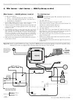
Страница 13: ...bustion ventilation air openings and vent system Fuel supply line in good condition and sized designed correctly Oil tank has oil and oil line valves are open Wiring installed per burner appliance ins...

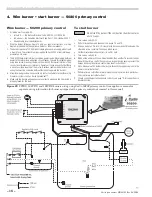
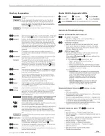
Страница 14: ...r 5 Make sure the burner and appliance are correctly wired and the line switch is properly fused for the load To start burner Do not start the burner if the combustion chamber contains oil or oil vapo...

Страница 15: ...Model 99FRD 100CRD 102CRD oil burners Instruction manual Carlin part number MN99102 Rev 08 20 08 15...

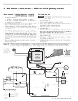
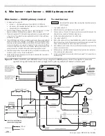
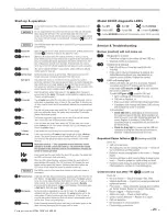
Страница 16: ...the burner 5 Make sure the burner and appliance are correctly wired and the line switch is properly fused for the load To start burner Do not start the burner if the combustion chamber contains oil or...

Страница 17: ...Model 99FRD 100CRD 102CRD oil burners Instruction manual Carlin part number MN99102 Rev 08 20 08 17...

Страница 18: ...or use with security fire alarm systems such as Carlin SecureHeat 6 Make sure the burner and appliance are correctly wired and the line switch is properly fused for the load To start burner Do not sta...

Страница 19: ...Model 99FRD 100CRD 102CRD oil burners Instruction manual Carlin part number MN99102 Rev 08 20 08 19...

Страница 20: ...als Operate all zones and verify that there is never a voltage reading at the meter A voltage reading indicates incorrect wiring that must be corrected before attempting to operate the burner 5 Alarm...

Страница 21: ...Model 99FRD 100CRD 102CRD oil burners Instruction manual Carlin part number MN99102 Rev 08 20 08 21...

Страница 22: ...with instruments a Check smoke It should be zero on the Bacharach scale b Set the appliance flue damper or barometric draft regulator so the draft or pressure in the vent complies with the appliance...

Страница 23: ...the appliance manual with the user Verify the user is aware of all procedures specified in the manuals Verify user will not store or use combustible liquids or materials or contaminants in the vicinit...

Страница 24: ...ting 22996S 11 C Air tube combustion head combination 21915 Two stage Suntec B2VA 8216 w fitting 23002S 13 Air tubes Single stage Danfoss BFPH w fitting 27813D 5 nominal approx 5 3 8 oal 44990 Single...

Страница 25: ...Model 99FRD 100CRD 102CRD oil burners Instruction manual Carlin part number MN99102 Rev 08 20 08 25 7 Repair parts continued...

Страница 26: ...rer s recommendations Any time you replace a component or disassemble any part of the burner for service maintenance perform a complete operational test after reassembly to verify the burner operates...

Страница 27: ...EZ Pro Burners that fall within the extended warranty period such defective parts should be returned freight prepaid to Carlin The repaired component or replacement part will be provided to the Custo...

Страница 28: ...at all Never attempt to use gasoline as a fuel for this burner as it is more combustible and could result in a serious explosion Never attempt to burn refuse or use any fuel other than 1 or 2 heating...

Отзывы: