background image

Model 99FRD, 100CRD, & 102CRD oil burners — Instruction manual

Carlin part number MN99102 Rev. 08/20/08

– 23 –

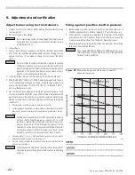
Verify burner/appliance operation

Check burner/appliance/controls operation

•  Test operating and limit controls on appliance as specified in appliance 

instructions.

•  Check  operation  of  the  primary  control  by  forcing  lockout  to  occur. 

For primary controls that enter latch-up after multiple lockouts, force 
latch-up to occur as well. Reset primary control per control data sheet 
instructions after each test. 

•  Start and stop the burner several times, allowing the primary control to 

sequence through normal operation. Verify correct operation of burner 
and primary control throughout.

Verify vent system operation

•  Verify vent is operating correctly and flue products are properly ex-

hausted  from  building.  If  the  building  contains  any  exhaust  fans  or 
conditions that could affect vent performance, check burner/appliance/
vent operation with exhaust fans (or other conditions) operating.

Combustion/ventilation air

•  Verify  combustion/ventilation  air  openings  are  not/will  not  be  ob-

structed.

•  Verify air opening louvers are full open.
•  If louvers are motor-operated, verify motor and end switch are inter-

locked with appliance/burner wiring to prevent operation of the burner 
if the air louvers are not fully opened.

Prepare burner for normal operation

•  Cycle burner off with appliance controls.
•  Turn off power to the appliance.
•  Seal the appliance flue damper test opening.
•  Verify all components and wires are in place and burner is ready for 

operation.

•  Restore power to the appliance.

Train the user

•  Train the user to operate the burner and appliance under normal condi-

tions.

•  Explain procedure to shut down burner/appliance when required.
•  Review the back cover of this manual (and the appliance manual) with 

the user.

•  Verify the user is aware of all procedures specified in the manuals.
•  Verify user will not store or use combustible liquids or materials or 

contaminants in the vicinity of the burner/appliance.

5.  Adjustment and verification 

(cont.)

Annual start-up & service

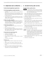
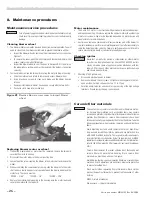
  This burner must be started and serviced at least annually 

by a qualified service technician. Failure to properly maintain 
and service the burner could result in severe personal injury, 
death or substantial property damage.

•  Discuss burner/appliance operation with user to determine any problems 

that may have occurred during the previous season and to verify user 
is aware of proper operation and care of the burner/appliance.

•  Review proper operation of the appliance/burner unit with the user.
•  Turn off power to appliance.
•  Remove combustion head assembly to clean and adjust if necessary. 

(See procedure on page 9.)

•  If the inside surface of the air tube and/or retention ring need to be 

cleaned, clean them with a vacuum cleaner with brush attachment 
while the combustion head assembly is out of the burner.

•  Replace the oil nozzle with the correct size specified in Table 1, page 

3.

•  Inspect and adjust the ignition electrodes and insulators per instructions 

on page 9 of this manual. Replace if proper spacing cannot be achieved 
or if components are damaged.

•  Close the housing cover plate and secure in place.
•  Inspect the fuel line oil filter. Replace if necessary.

  Oil line filters — Use a non-bypassing filter to prevent nozzle 

plugging caused by poor oil filtration. Non-bypassing filters 
prevent small foreign particles from bypassing the filter, a 
common  problem  with  fiber  element  type  filters. Another 
problem of some filters is the fiber from filter element tears 
can break away and plug the nozzle or fuel unit.

•  Perform the complete checkout procedures of pages 13 to 23, including 

system inspection and checks.

•  Inform the user of any problems found.

6.  Annual start-up and service

Содержание 100CRD

Страница 1: ...y stated other wise this manual must be used only by a qualified service technician Failure to comply with this or other requirements in this manual could result in severe personal injury death or sub...

Страница 2: ...w Train the user To properly operate the burner appliance per this manual and the appliance instructions see User s information To keep this manual at or near the burner appliance for ready ac cess by...

Страница 3: ...ctions when appliance data is not available Table 1 Apply the guidelines below to select a nozzle when appliance specific nozzle data is not avialable from the manufacturer See notes at end of table f...

Страница 4: ...uvers screens Air opening sizes are always given in free area This means after deduction for louver obstruction If you can t find the louver reduction for the grilles used assume free area is 20 of to...

Страница 5: ...ponents maintain all necessary clearances to combustible construction including the correct design of thimbles and insulation where penetrating combustible walls Illustrations A to F in Figure 1 show...

Страница 6: ...surfaces dry base design E Chamber with refractory floor and water backed target wall without target refractory lining F Chamber with refractory floor and water backed target wall with target refrac t...

Страница 7: ...spirit level Adjust flange if needed 7 The end of the air tube should be flush or almost flush with the inside of the combustion chamber wall 8 Verify the air tube is level and inserted the correct d...

Страница 8: ...sertionmethods are intended only for negative overfire pressure For pressur ized firing you must obtain a burner with a welded flange designed for use with the specific appliance Failure to comply cou...

Страница 9: ...from escaping from the housing Replace the gasket if not in good condition 9 Inspect the ignitor contact clips Clean or replace if necessary to ensure reliable contact with the electrodes Install noz...

Страница 10: ...tely inserted into the housing collar and the Set initial burner air settings Combustion head 1 The combustion head adjusting slide controls the spacing between the retention ring and throttle ring or...

Страница 11: ...02CRD oil burners Instruction manual Carlin part number MN99102 Rev 08 20 08 11 3 Prepare burner continued Figure 13 Combustion head air tube combinations typical Table 3 Approximate air band and comb...

Страница 12: ...ctly sized and installed and that the fuel flow is unob structed the oil tank is clean and only 1 or 2 heating oil are supplied Failure to supply a reliable oil flow could result in loss of heat and p...

Страница 13: ...bustion ventilation air openings and vent system Fuel supply line in good condition and sized designed correctly Oil tank has oil and oil line valves are open Wiring installed per burner appliance ins...

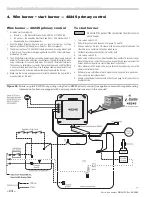
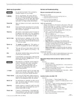
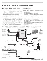
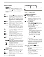
Страница 14: ...r 5 Make sure the burner and appliance are correctly wired and the line switch is properly fused for the load To start burner Do not start the burner if the combustion chamber contains oil or oil vapo...

Страница 15: ...Model 99FRD 100CRD 102CRD oil burners Instruction manual Carlin part number MN99102 Rev 08 20 08 15...

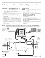
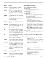
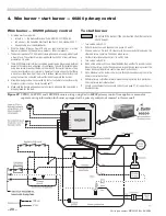
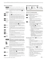
Страница 16: ...the burner 5 Make sure the burner and appliance are correctly wired and the line switch is properly fused for the load To start burner Do not start the burner if the combustion chamber contains oil or...

Страница 17: ...Model 99FRD 100CRD 102CRD oil burners Instruction manual Carlin part number MN99102 Rev 08 20 08 17...

Страница 18: ...or use with security fire alarm systems such as Carlin SecureHeat 6 Make sure the burner and appliance are correctly wired and the line switch is properly fused for the load To start burner Do not sta...

Страница 19: ...Model 99FRD 100CRD 102CRD oil burners Instruction manual Carlin part number MN99102 Rev 08 20 08 19...

Страница 20: ...als Operate all zones and verify that there is never a voltage reading at the meter A voltage reading indicates incorrect wiring that must be corrected before attempting to operate the burner 5 Alarm...

Страница 21: ...Model 99FRD 100CRD 102CRD oil burners Instruction manual Carlin part number MN99102 Rev 08 20 08 21...

Страница 22: ...with instruments a Check smoke It should be zero on the Bacharach scale b Set the appliance flue damper or barometric draft regulator so the draft or pressure in the vent complies with the appliance...

Страница 23: ...the appliance manual with the user Verify the user is aware of all procedures specified in the manuals Verify user will not store or use combustible liquids or materials or contaminants in the vicinit...

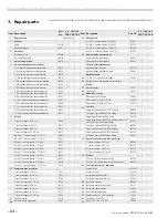
Страница 24: ...ting 22996S 11 C Air tube combustion head combination 21915 Two stage Suntec B2VA 8216 w fitting 23002S 13 Air tubes Single stage Danfoss BFPH w fitting 27813D 5 nominal approx 5 3 8 oal 44990 Single...

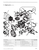
Страница 25: ...Model 99FRD 100CRD 102CRD oil burners Instruction manual Carlin part number MN99102 Rev 08 20 08 25 7 Repair parts continued...

Страница 26: ...rer s recommendations Any time you replace a component or disassemble any part of the burner for service maintenance perform a complete operational test after reassembly to verify the burner operates...

Страница 27: ...EZ Pro Burners that fall within the extended warranty period such defective parts should be returned freight prepaid to Carlin The repaired component or replacement part will be provided to the Custo...

Страница 28: ...at all Never attempt to use gasoline as a fuel for this burner as it is more combustible and could result in a serious explosion Never attempt to burn refuse or use any fuel other than 1 or 2 heating...

Отзывы: