background image

13

edge. Apply narrow (1/16" [2mm]) strips of tape over the lines 
so you will be able to feel them when lifting the model with 
your fi ngers. 

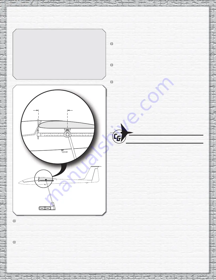
This is where your model should balance for the fi rst 

fl ights. Later, you may experiment by shifting the C.G. 1/8" 
[3mm] forward or 1/8" [3mm] back to change the fl ying 
characteristics. Moving the C.G. forward will improve 
the smoothness and stability, but the model will then be 
less sensitive (which may be fi ne for less-experienced 
pilots). Moving the C.G. aft makes the model more 
maneuverable and improves the sailplane’s response to 
air currents. In any case, start at the recommended 
balance point 
and do not at any time balance the model 

outside the specifi ed range.

3-5/8" [92mm]

 2. With the wing attached to the fuselage, and all parts of 

the model installed (ready to fl y), place the model right side 
up on a Great Planes CG Machine, or lift it at the balance 
point you marked.

 3. If the tail drops, the model is “tail heavy.” Weight will need 

to be added to the nose to get the model to balance. If the 
nose drops, the model is “nose heavy.” If needed, the receiver 
and receiver battery can be moved aft of the servos. If weight 
is required use Great Planes “stick-on” lead (GPMQ4485). 

To fi nd out how much weight is required, place incrementally 

increasing amounts of weight on the top of the fuselage over 
the location where it would be mounted inside until the model 
balances. The Sophisticated Lady has a weight compartment 
in the nose where lead or BBs can be added. Once the amount 
of weight that is required in the nose is determined, the BBs 
can be glued in using white glue.

 4. IMPORTANT: If you found it necessary to add any weight, 

recheck the C.G. after the weight has been installed.

BALANCE THE MODEL LATERALLY

 1. With the wing level, have an assistant help you lift the 

model by the nose and the bottom of the fuse under the TE 
of the fi n. Do this several times.

 2. If one wing always drops when you lift the model, it means 

that side is heavy. Balance the airplane by adding weight 
to the other wing tip. An airplane that has been laterally 
balanced will track better.

CHECKING FOR WARPS

This is a very important step and should be done occasionally 

throughout the fl ying season. A sailplane’s wing is most effi cient 
when it is not twisted or warped at all. “Washout” (the wing’s 
trailing edges are twisted up at the tips) helps make a poor 
wing design fl y better by adding some stability (preventing 
stalls) at slow speeds but it cuts down on the wing’s effi ciency 
at normal speeds. The Sophisticated Lady ARF’s wing is 
designed to fl y well at slow speeds without any washout, and 
therefore we recommend you check to make sure the wings 
are “fl at” using the following procedure:

Set the wing so an inner panel is resting on a fl at surface. Any 
warp (twist) will show up by causing a corner of the panel to 
rise off the work surface. 

To remove the warp, gently twist the wing in the opposite 

direction while a helper glides an iron or heat gun over the 
covering on both the top and the bottom of the panel to re-
shrink the covering. Hold the twist until the covering cools 
and then recheck for warps. It may take several tries to get a 
warp out, but it is worth it as you will end up with a sailplane 
that fl ies straight and true and responds to air currents like a 
high performance sailplane should. 

Follow the same procedure to check all four wing panels and 
then go back and double check them. Sometimes you put a 
warp in one wing panel while trying to fi x another. You should 
also look at the tail surfaces as they too can warp. 

Содержание Sophisticated Lady GPMA1959

Страница 1: ... pilot for added realism and aT tail for smoother handling in turbulence GPMA1959 Wingspan 78 in 1980 mm Wing Area 674 in 43 5 dm Weight 27 30 oz 765 850 g Wing Loading 5 8 6 4 oz ft 18 20 g dm Length 42 in 1060 mm Requires 2 channel radio with 2 servos hi start Recommended Products FUTK6900 Futaba 6EX 6 Channel FASST 2 4GHz Computer Radio FUTM0004 2 Futaba S3004 Standard Ball Bearing Servos HCAM6...

Страница 2: ... act of using the user assembled product the user accepts all resulting liability If the buyer is not prepared to accept the liability associated with the use of this product the buyer is advised to return this kit immediately in new and unused condition to the place of purchase To make a warranty claim Hobby Services send the defective part 3002 N Apollo Dr Suite 1 or item to Hobby Services Champ...

Страница 3: ...ries required to finish the Sophisticated Lady ARF Order numbers are provided in parentheses 1 4 Foam Rubber GPMQ1000 64 Rubber Bands HCAQ2020 ADHESIVES AND BUILDING SUPPLIES In addition to common household and hobby tools this is the short list of the most important items required to assemble the Sophisticated Lady ARF Great Planes Pro CA glue is recommended Thin CA 1 2 oz 15g Thin Pro CA GPMR600...

Страница 4: ...ve any excess material from the joiner to allow the panels to fit together Gather everything required for gluing the wing joiner and wing together including 30 minute epoxy mixing sticks epoxy brush 12 304mm long dowel or wire denatured alcohol and paper towels Mix up 1 2 oz 14 8cc of 30 minute epoxy Working quickly pour a generous amount into the joiner pocket of one wing half Use your wire or do...

Страница 5: ...dhere to it Position the fin on the fuselage and move the cable to check that it moves freely 4 Use 6 minute epoxy to glue the fin to the top of the fuselage Wipe off the excess epoxy with a paper towel dampened with rubbing alcohol Use masking tape to hold the fin in position aligned with the centerline of the fuselage and parallel to the sides Drill a 3 32 Hole 1 2 Deep in the Center of the Hing...

Страница 6: ...E STABILIZER 1 Draw a centerline on the bottom of the stabilizer Draw a line 3 32 2 4mm on each side of the centerline Use a hobby knife to cut and remove the covering only between the two outside lines DO NOT cut the wood under the covering as this will weaken the stabilizer causing it to fail 2 Use 6 minute epoxy to glue the stabilizer to the top of the fin Use a square to check that the stabili...

Страница 7: ...nd harden the holes by applying two or three drops of thin CA in each hole After the CA has cured attach the control horn to the rudder using two 2 56 x 3 8 9 5mm screws and the control horn back plate 3 Use a 44 or 3 32 2 4mm drill bit to enlarge the outer hole in the second nylon control horn 4 Insert the quick connector through the previously drilled hole in the control horn Install a 2mm washe...

Страница 8: ...d receiver battery in 1 4 6 4mm thick foam Position the receiver and receiver battery in the fuselage as shown Remove the receiver switch cover from the receiver switch Position the switch cover on the outside of the fuselage between the receiver and receiver battery Mark the two mounting screw holes and the switch opening on the fuselage Use a sharp hobby knife to cut out the switch opening and a...

Страница 9: ...od outer pushrod tube supports over the elevator outer pushrod tube 12 Center the elevator servo Trim a servo arm to fit perpendicular to the elevator servo Remove the other unused servo arms 13 Install a quick connector on the elevator servo arm following the same procedure used to install it on the elevator control horn 14 Install the servo arm on the elevator servo Route the elevator cable thro...

Страница 10: ...ockpit to make sure it will not affect the plastic RC car paints usually work well for this Do not paint the edges of the cockpit where the canopy will attach or the glue will not hold as well After the canopy is glued on the canopy frame decal will cover the glue joint After the paint has dried apply the instrument decal to the instrument panel 2 Using a needle nose pliers open the eyelet slightl...

Страница 11: ... sparingly 7 Remove the canopy and install the wing Only a couple of large rubberbands are needed to hold the wing at this time You will need to use at least eight rubber bands for flying 8 Trim the aft end of the canopy to follow the shape of the wing 9 Attach the threaded tow hook to the bottom of the fuselage by threading a 3mm nut and a 3mm washer all the way onto the tow hook Apply a drop of ...

Страница 12: ...n the servo arms 2 With the transmitter and receiver still on check all the control surfaces to see if they are centered If necessary adjust the clevises on the pushrods to center the control surfaces ELEVATOR MOVES DOWN RUDDER MOVES RIGHT 2 Channel Radio Set Up Standard Mode 2 3 Make certain that the control surfaces respond in the correct direction as shown in the diagram If any of the controls ...

Страница 13: ...OTE The throws are measured at the widest part of the elevator and rudder These are the recommended control surface throws HIGH RATE LOW RATE ELEVATOR 3 8 9 5mm 22 deg Up 3 8 9 5mm 22 deg Down 3 16 4 8mm 11 deg Up 3 16 4 8mm 11 deg Down RUDDER 1 1 2 38mm 24 deg Right 1 1 2 38mm 24 deg Left 1 25 4mm 16 deg Right 1 25 4mm 16 deg Left BALANCE THE MODEL C G More than any other factor the C G center of...

Страница 14: ...after the weight has been installed BALANCE THE MODEL LATERALLY 1 With the wing level have an assistant help you lift the model by the nose and the bottom of the fuse under the TE of the fin Do this several times 2 If one wing always drops when you lift the model it means that side is heavy Balance the airplane by adding weight to the other wing tip An airplane that has been laterally balanced wil...

Страница 15: ...otifying the airport operator I will give right of way and avoid flying in the proximity of full scale aircraft Where necessary an observer shall be utilized to supervise flying to avoid having models fly in the proximity of full scale aircraft 3 Where established I will abide by the safety rules for the flying site I use and I will not willfully and deliberately fly my models in a careless reckle...

Страница 16: ...be able to launch it at just the right speed so it soars straight ahead in a long and impressive glide path Adjust the trims on your transmitter to get the plane to fly straight ahead in a smooth glide path Once you get the hang of launching it you can try turning the plane during the trim flights by gently applying a touch of right or left rudder You can also try flaring the landing by slowly app...

Страница 17: ... direction the plane is flying and look over your shoulder to watch the model Don t worry about accomplishing very much on your first flights Use these flights to get the feel of the controls and the Sophisticated Lady ARF s flying characteristics Try to keep the plane upwind and just perform some gentle S turns always turning into the wind until it is time to set up for landing Have a helper adju...

Страница 18: ...plane getting too high don t dive the plane to get out of the lift Sailplanes are very efficient aircraft and they will build up a lot of speed and could come apart in the rough air of a thermal The easiest way to lose altitude is to apply full rudder and full up elevator This will put the sailplane into a tight spin that will not over stress the airframe but it will enable it to lose altitude ver...

Страница 19: ...or away from the sink both of which are desirable BALLASTING In strong wind conditions you may want to add ballast weight to the sailplane to increase its wing loading which increases its normal flying speed Increasing the weight of your sailplane does not change its glide ratio but it does make it fly faster Because of the faster sink rate you need to be very cautious when ballasting for a therma...

Страница 20: ...19 ...

Страница 21: ...Entire Contents 2011 Hobbico Inc All rights reserved GBGA1059 v1 1 Mnl www carlgoldbergproducts com ...

Отзывы: