RUDDER & ELEVATOR CONTROL HORN
INSTALLATION
1.
!
Collect the following items:
(1) Rudder
(1) Elevator
(2) Control horn
(4) 2-56 x 3/4" machine screw
(1) Double sided control horn
(1) 2-56 x 1/2” philups head screw
2.
!
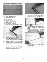
Measuring from the fuselage side, make a
mark on the elevator hinge line 5/8" from the
fuse.
3.
!
Place the center of the control horn on the
mark and the hinge line and mark the loca-
tion of the screw holes on the elevator.
!
Using a 5/64" drill bit, drill the holes through
the elevator.
!
Using two 2-56 x 3/4" screws, screw the
control horn and the backplate tightly to the
elevator.
!
Repete these steps for the other elevator.
NOTE:
The double-sided control horn may be found
in the tailwheel assembly package.
4.
!
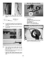
Place the control horn in the rudder notch, as
shown. The control horn must be even with
the hinge line. When you are satisfied with
the fit, mark the location of the screw hole
and drill, using a 3/32” bit.
!
Mount the control horn, using the 2-56 x 3/4”
phillips head screw.
RUDDER & ELEVATOR INSTALLATION
1.
!
Collect the following items.
(1) Fuselage/Tail Assembly
(2) Elevators
(1) Rudder
(12) Jet hinges
3.
!
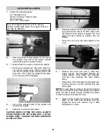
Remove the pins in each hinge and, keeping
the elevator/stab assembly in position, apply
3 or 4 drops of thin CA to each hinge, on both
the top and bottom sides of the stab.
!
Allow ten minutes for the CA to cure before
flexing the elevator. Then install the second
elevator.
2.
!
Take four hinges and, as with the aileron
hinge installation, insert the hinge into the
elevator, using straight pins to ensure the
hinge stays centered between the stabilizer
and the elevator.
!
Slide the exposed side of the hinge into the
slots in the stab until the pins touch both the
stab and the elevator.
4.
!
When the elevators have cured, install the
hinges and mount the rudder, using the same
techniques used for the other hinged sur-
faces.
NOTE:
Before gluing, make sure the top of the rud-
der is even with the top of the fin.
11
Содержание decathlon arf
Страница 29: ......

