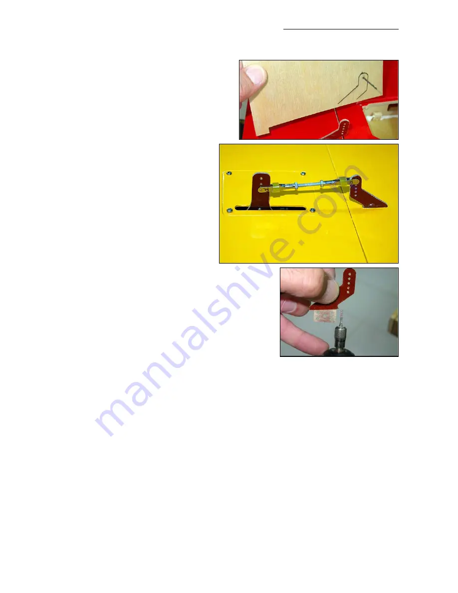
forget to allow for the extra thickness of the C-
ARF servo horns that will be fixed onto the servo
discs. You may need to make the slots in the
servo hatch covers a little wider, by 1mm or so.
Tack glue the servo mounts to the hatch covers
with CA, then remove the servos and reinforce
the glue joints between the servo mount and the
servo cover plate with slow (min. 30
minute) epoxy and milled fibre, with a nice
glue fillet all around. These are important
joints!
Centre the servos using your R/C and fit
the C-ARF phenolic servo arms to the
servo output discs using the same method
as for the elevator servos. Secure with 2
small bolts and nuts each. Fix the covers
to the wing with 4 sheet-metal screws Ø
2.9 x 10mm.
Finally make up the linkages from the M3
x 60mm threaded rods supplied, with 2
clevises and 2 x M3 locknuts for each.
Important:
The clevise should be on the
inner
hole of the
servo extension arm, and on the aileron horn it should be on
the
outer hole
from the aileron surface - to maximise the
mechanical advantage and reduce any chance of flutter.
With your transmitter throws set at maximum (125%) this will
still allow even the hi-rate/3D throws mentioned at the end of
the manual. Please do
not
use the outer hole on the servo
arm, and do
not
reduce the throws electronically in your
transmitter !
Don’t forget to ‘Loctite’ the clevise and lock-nut on one end of each linkage, and fit short lengths
of tube to prevent clevises from opening accidentally. Do NOT use single-sided ball-links on the
phenolic horns, because they will twist the servo arm and cause flutter. This is a solid experience
and you should consider it a FACT.
Motor Installation
The new Composite-ARF 2.12m design allows so many different choices of power unit that it’s
impossible to provide mounting bulkheads & hardware for all of them! Therefore, depending on
your choice of gas/methanol engine you may need to modify the ‘generic’ milled plywood parts
we have included, or even make a few of your own. It should also be possible to fit a Hacker C-
50 or Plettenberg Xtra outrunner electric installation, using the ‘Electric Option pack’ originally
designed for our Extra 2 x 2 (Product #610900), but of course you will need to modify the fire-
wall and supports to fit.
The original prototype was flown with a DA-50, probably the top end of the power range that any-
Composite-ARF Extra 300L
(2.12m/84”)
21


