


Carefree of Colorado
Installation
Manual
T
RAVEL
'
R
052540-002r14
5
STOP
–
If using the optional arm extension for mounting, follow the directions for "Assembling the Awning" and
"Mounting the Awning" in Installation supplement 052540-102 - "Travel'r Arm Extension".
A
SSEMBLING THE
A
WNING
1.
Decide on the location of the switch to determine the cable routing.
2.
If the motor cable is to be routed through the RV wall at the bottom of the arm, slip the cable through
the slot at the bottom of the track (refer to page 8). Go to step 4.
3.
If the motor cable is to be routed through the RV wall at the top of the arm:
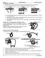
3.1 Remove the plastic wrap at the top of the motorized arm. Partially open the arm being careful to
not let the arm extend more than 6”.
CAUTION
The arm is under tension from the gas shock located in the arm.
When the wrap is removed, the arm will try to open completely. Firmly hold the arms
closed while removing
the wrap
.
3.2 Pull the motor cable from the back of channel and out the hole in the top of the channel.
3.3 Close the arm.
3.4 Secure the top of the arm in the closed position using a plastic wrap or equivalent.
4.
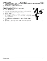
For Aftermarket and Upgrade Installations:
On each arm attach the top mounting bracket to the channel using
the screw and nut and as shown.
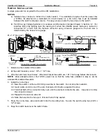
5. Align the roller assembly with the end cap on the motorized arm
assembly. Rotate the end cap until the slot in the cap aligns with
the empty slot in the roller assembly, and then press the roller
assembly fully into the cap. The end cap must seat squarely over
the end of the roller assembly when complete.
NOTE: The roller assembly must be
oriented with the fabric going over the
roller toward the mounting surface.
6. Secure the end cap to the roller assembly using
two #10 square-drive screws.
7. Repeat steps 5 and 6 to attach the non-
motorized arm assembly to the roller assembly.
NOTICE
During assembly and installation, The arm assemblies must remain perpendicular to
the roller assembly. Failure to handle the arm assemblies carefully can bend the drive shaft.
Top Mounting
Bracket
#10 x 2 Screw
#10 Nylock Nut
TravelR022
Roll Bar
Assembly
End Cap
#10 x 5/8 Screw
End Cap
#10 x 5/8 Screw
TravelR004
Align Slots
Align Slots