Step 11
Level and Square
58
docs.carbide3d.com
59
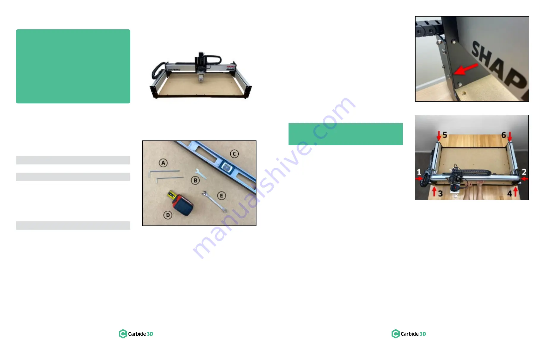
Required Tools
See
Figure 11‑2
:
Item Description
Qty
A
3 and 4mm Hex Key
1
B
10mm Wrench
1
C
Level (not included)
1
Recommended Tools
See
Figure 11‑2
:
Item Description
Qty
D
Tape Measure
1
E
10mm Combination Wrench
1
Confirm Level
The baseframe received a preliminary leveling in step 2.
1.
Double-check for level now at several different points across the machine: front-to-back, side-to-side,
and diagonally. Adjust the four (4) leveling feet where necessary.
Confirm Tension of the V‑Wheels
The V-wheels were tensioned in step 4.
1.
Double-check each one now and adjust where necessary. Refer back to
Figure 3‑4
and
3‑5
(page 18)
for a detailed explanation of eccentric nuts and instructions on tensioning V-wheels.
Square the Machine
The machine is gradually brought into square by
first loosening all structural support screws, then
tightening again while
SIMULTANEOUSLY
holding
the X-rail parallel to the front and rear endplates.
1. Use the 4mm hex key to loosen all twenty-four
(24) M6x12mm button head cap screws 1
/
2
turn
back from snug (there are four (4) in the ends of
each aluminum extrusion rail).
2. If necessary, use the 3mm hex key to loosen
the fifteen (15) M5x25mm button head screws
securing the baseplate to baseframe (these
screws were not tightened in step 2).
3.
With all thirty-nine (39) structural screws now
loose,
HOLD
the X-rail
FORWARD
, bringing
both Y-carriage plates squarely into contact
with the front endplate. See
Figure 11‑3
.
4. Maintain
FORWARD PRESSURE
and use the
4mm hex key to fully tighten the sixteen (16)
M6x12mm button head cap screw sets 1-4, in
numbered order, shown in
Figure 11‑4
.
5.
Move the X-rail to the rear and maintain
REARWARD PRESSURE
and use the 4mm hex key to fully tighten the eight (8) M6x12mm button head
cap screw sets 5-6, in numbered order, shown in
Figure 11‑4
.
6.
Use the 3mm hex key to fully tighten the fifteen (15) M5x25mm button head cap screws of the MDF
baseplate.
Congratulations! Assembly is now complete!
Next Steps
On the following pages you will find helpful information to get you ready to use your Shapeoko XL.
1. Connect to Power
2.
Download the Software
3.
Configure
Carbide Motion 5
4. Run the Test Project
5. Workholding
6. Cutting Tutorials & Projects
7. User Guides & Video Tutorials
PRO TIP:
During this step of the assembly, it
may be helpful to have another set of hands.
Figure 11-2
Figure 11-3
Figure 11-4
Содержание Shapeoko XL
Страница 1: ......


