background image

Via Hub 

Configuration Manual

July 2017 • Rev. 1.1

Page

of

8

10

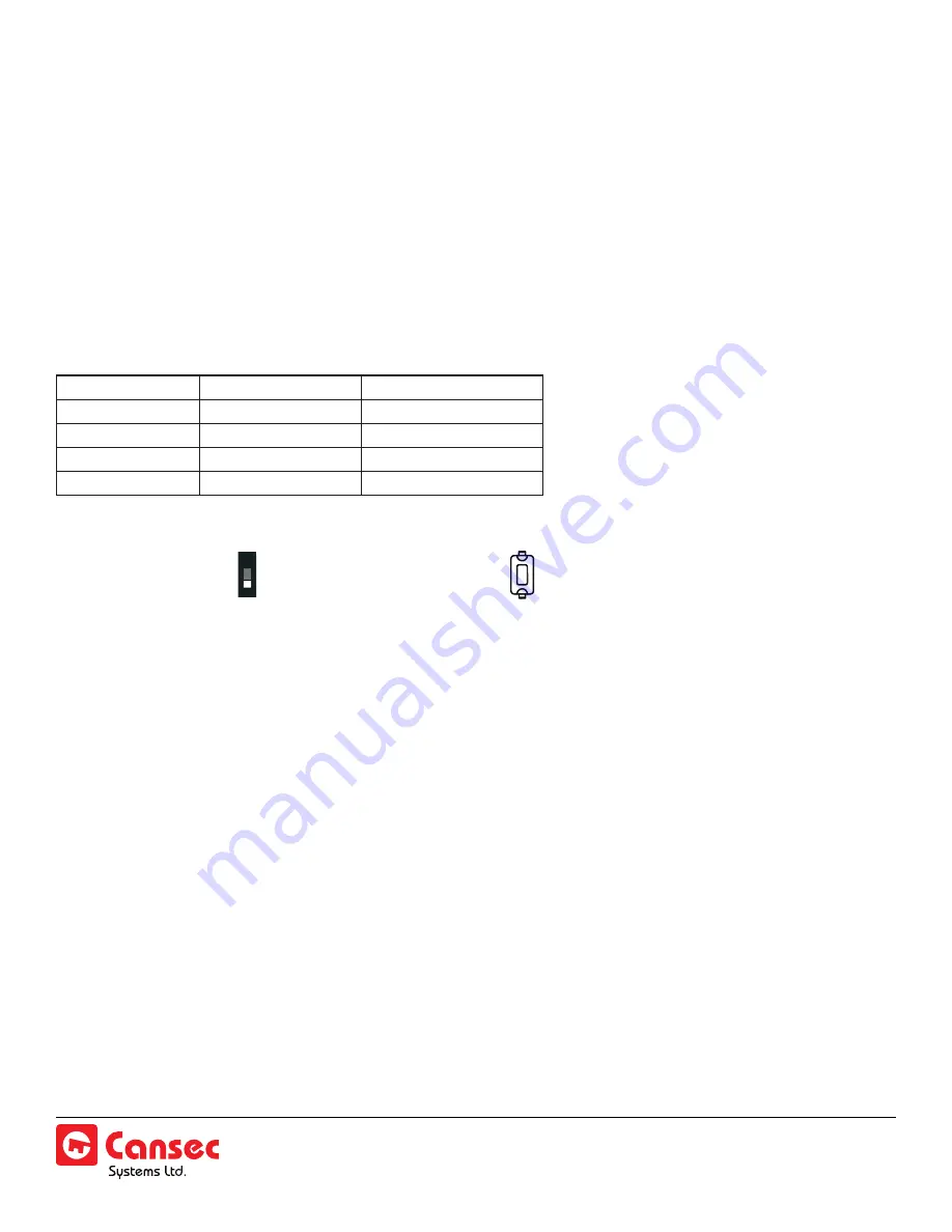
DIP SWITCH “D”        & RESET BUTTON “E”

ON

When settings are changed on DIP switches A, B & C. The new data must be stored in memory. 
To do this, slide DIP switch “D” to UP (ON) and press the RESET button “E”. Once the data has 
been stored, the 4 onboard relays will cycle on and off. Slide DIP switch “D” to DOWN (OFF) and 
press the RESET button “E” again to enter normal operation mode. 

POWER LEVEL SETTING STRATEGY

By default, the power levels for the Via Lock and Via Hub are set to LOW. This provides a range of 
approx. 70’ range in a typical office environment. When the power level of the Via Lock and Hub 
are BOTH set to HIGH, this range is extended to approx. 170’.

If a reader connects and communicates reliably, the power setting should be left at LOW on both 

the Via Lock and the Hub as it will extend the battery life on the Via Lock.

If either Via Lock is set to HIGH power, the associated Hub must also be set to HIGH power. When 

a Via Lock and Hub are set to HIGH power to accommodate a distance in excess of 70’, a second 

reader located at 70’ or less can still be left on LOW power.

Acceptable power combinations are shown below:

Via Lock1

Via Lock2

Via Hub

Power Level LOW

Power Level LOW

Power Level LOW

Power Level LOW

Power Level HIGH

Power Level HIGH

Power Level HIGH

Power Level LOW

Power Level HIGH

Power Level HIGH

Power Level HIGH

Power Level HIGH

Содержание Via Lock1

Страница 1: ...July 2017 Cutting edge simplicity VIA HUB INSTALLATION MANUAL...

Страница 2: ...he associated access control panel for verification If the lock relay operates indicating that access is granted the Hub will send a wireless unlock command to the reader at which the card was present...

Страница 3: ...PANEL 2 4 GHzWIRELESS TYPICAL RANGETO 70 170 FT 21 52 M VIA WIRELESS LOCK 1 VIA WIRELESS LOCK 2 ACCESS CONTROL PANEL FORCEDENTRYOUTPUT LOW BATTERY OUTPUT FORCED ENTRY OUTPUT LOW BATTERY OUTPUT Specif...

Страница 4: ...RN Configure Via Hub DIP SWITCHES DIP SWITCH A ADDR Do not change the default settings Switch A1 sets to DOWN ON switches A2 A8 set to UP OFF DIP SWITCH B NET ID Switches B1 B6 are used to set a Netwo...

Страница 5: ...DOWN OFF ON DOWN 14 OFF OFF ON DOWN ON DOWN ON DOWN OFF 15 OFF OFF ON DOWN ON DOWN ON DOWN ON DOWN 16 OFF ON DOWN OFF OFF OFF OFF 17 OFF ON DOWN OFF OFF OFF ON DOWN 18 OFF ON DOWN OFF OFF ON DOWN OFF...

Страница 6: ...N DOWN ON DOWN OFF ON DOWN 46 ON DOWN OFF ON DOWN ON DOWN ON DOWN OFF 47 ON DOWN OFF ON DOWN ON DOWN ON DOWN ON DOWN 48 ON DOWN ON DOWN OFF OFF OFF OFF 49 ON DOWN ON DOWN OFF OFF OFF ON DOWN 50 ON DOW...

Страница 7: ...OCK CMD WIEGAND UNLOCK CMD WIEGAND LOCK RELAY LOCK RELAY ANY ACCESS CONTROL PANEL DOOR 1 DOOR 2 12VDC FROM ACCESS CONTROL PANEL UNIT ID 1 NETID 63 ACCESS CONTROL PANEL FORCEDENTRYOUTPUT LOW BATTERY OU...

Страница 8: ...en the power level of the Via Lock and Hub are BOTH set to HIGH this range is extended to approx 170 If a reader connects and communicates reliably the power setting should be left at LOW on both the...

Страница 9: ...D E 4 RELAYS ON SW4 SW2 NET ID ADDR SW6 SW1 SW3 PWR GND BPR LED D1 D0 PWR GND BPR LED D1 D0 IN1 GND IN2 GND IN3 GND IN4 GND GND A B B A GND OP4 OP3 OP2 OP1 12VDC GND READER 2 READER 1 J9 J10 J12 J11...

Страница 10: ...USE FACTORY DEFAULT J7 J6 J13 J14 J2 J5 J8 D1 D0 DOOR 1 D1 D0 DOOR 2 12VDC IN GND DOOR CONTACT OUTPUT FOR DOOR 1 CHANNEL ON cansec com SMARTLOCK PRO PLUS N C N O N C N C N O N O PWR GND BPR LED D1 D0...

Отзывы: