background image

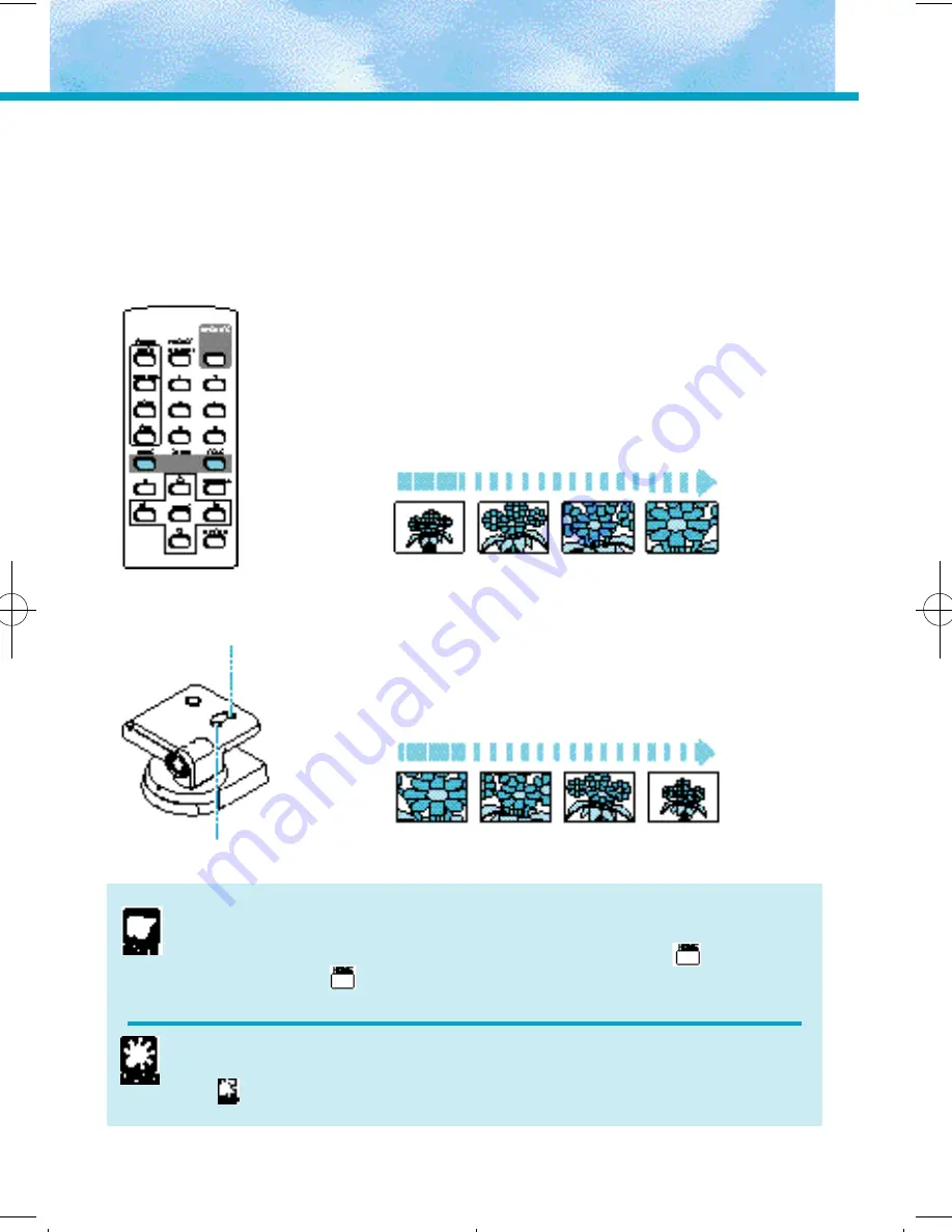
Zooming In/Out 

(TELE/WIDE)

The zoom function increases and decreases the size of the subject on the monitor
screen. You can zoom in and out using the zoom buttons on the camera head or on
the wireless controller.

To zoom in (increase the subject size)

Press the  / button.

Holding down the button increases the rate of
zoom.

Slow

Fast

To zoom out (decrease the subject size)

Press the 

/

button.

Holding down the button increases the rate of
zoom.

Slow

Fast

21

Zoom-out  button

Zoom-in  button

Take care not to change the camera head angle when you use the
zoom buttons on the camera head.
If you do change the camera head angle, always press the 

button. If you

do not press the 

button, it will no longer be possible to correctly adjust

the camera head angle.

Focusing Range
The VC-C3 may not be able to focus depending on the zoom position.Refer
to “

Focusing Range” on P.20.

*VC-C3/E/US/QX3.32  5/29/01  3:26 PM  Page 21

Содержание VC-C3

Страница 1: ...truction manual carefully before operation Be sure to read the Safe Use of Equipment section before using this equipment Store this manual in a readily accessible location for future reference E ENGLISH INSTRUCTION MANUAL ...

Страница 2: ...g your VC C3 cannot be used in ways that infringe copyright laws or without the consent of the owner unless intended for personal use only Notes 1 The unauthorized transfer of all or any part of the contents of this Manual is forbidden 2 The contents of this Manual are subject to change without notice 3 Every effort has been made to ensure that this Manual is flawless However if you find any overs...

Страница 3: ...tain this book as a permanent record of your purchase to aid identification in case of theft Date of Purchase Dealer Purchased from Dealer Address Dealer Phone No Model No VC C3 Serial No Important Operational Instructions WARNING TO REDUCE THE RISK OF ELECTRIC SHOCK DO NOT EXPOSE THIS EQUIPMENT TO RAIN OR MOISTURE CAUTION TO REDUCE THE RISK OF ELECTRIC SHOCK AND TO REDUCE ANNOYING INTERFERENCE US...

Страница 4: ...y to correct the interference by one or more of the following measures Reorient or relocate the receiving antenna Increase the separation between the equipment and receiver Connect the equipment into an outlet on a circuit different from that to which the receiver is connected Consult the dealer or an experienced radio TV technician for help Use of shielded cable is required to comply with class B...

Страница 5: ... to a child or adult and serious damage to the equipment An equipment and cart combination should be moved with care Quick stops excessive force and uneven surfaces may cause the equipment and cart combination to overturn 9 Power Sources The PA V12 AC Adapter should be operated only from the type of power source indicated on the marking label If you are not sure of the type of power supply to your...

Страница 6: ...t from the wall outlet and all power sources including battery and refer servicing to qualified service personnel under the following conditions a When the power supply cord or plug is damaged b If any liquid has been spilled onto or objects have fallen into the equipment c If the equipment has been exposed to rain or water d If the equipment does not operate normally even if you follow the operat...

Страница 7: ...Do not subject the equipment to strong impacts 24 Please observe the following when handling the batteries Failure to do so can result in the batteries bursting or emitting heat sparks or corrosive fluid Do not throw the batteries into a fire and do not heat short circuit or attempt to disassemble the batteries Do not attempt to recharge the batteries Do not use batteries other than those specifie...

Страница 8: ...e Combined 13 Loading the Batteries into the Wireless Controller 14 Operable Range of the Wireless Controller 14 The LEDs 15 Using the VC C3 16 Turning the Units ON and OFF 16 Operations 18 Changing the Camera Head Angle Pan Tilt Home Position 18 Focusing FOCUS 19 Zooming In Out TELE WIDE 21 Adjusting the Brightness BRIGHTNESS 23 Storing a Preset Position Restoring a Preset Position 23 OPERATE Mod...

Страница 9: ... Use the VC C3 Checking the Accessories Camera CCU Camera control unit Camera head and base Wireless controller AC adapter CCU camera control unit cable Pin cable 6 strips of Velcro Instruction Manual Warranty Card ...

Страница 10: ...mputer etc Not used in normal use 1 When the extension button is pressed the VC C3 transmits a signal to the computer This means that some software can attach the camera detection function to the extension button If the settings are changed switch the VC C3 OFF and ON again These switches should be set when you connect the VC C3 to the computer consult your authorized Canon dealer P 35 SW1 SW2 SW3...

Страница 11: ...e camera head up down left and right HOME Moves the camera head to the center BRIGHTNESS button P 22 Adjusts the brightness ZOOM button P 21 TELE Zoom in WIDE Zoom out Number buttons Stores preset positions P 23 Restores preset position P 23 Selects ID numbers P 26 27 ID button P 25 29 Select or cancel ID numbers Battery cover See P 14 for information on loading batteries OPERATE button P 24 Switc...

Страница 12: ...e computer connection cable differs depending on the type of computer used Check with your dealer 3 If your VC C3 is connected to external speakers the sound made by the camera head motor when it operates will be audible through the speakers AC 120 V to a computer to S VIDEO IN to monaural AUDIO IN 3 or VIDEO IN AC adapter CCU cable Computer connection cable 1 2 S VIDEO cable 1 Pin cable Ensure th...

Страница 13: ...parated Use the Velcro strips to adhere the camera and the camera control unit firmly to a flat stable surface When the Camera and the Camera Control Unit are Combined Use the tripod screw to fix the camera to the camera control unit and then use the Velcro strips provided to adhere the camera control unit firmly to a flat stable surface 13 Velcro Camera Camera Tripod socket Tripod screw Camera an...

Страница 14: ...reless controller varies depending on the amount of charge remaining in the batteries and interference from other objects 14 Before You Use the VC C3 Please observe the following when handling the batteries Failure to do so can result in the batteries bursting or emitting heat sparks or corrosive fluid Do not throw the batteries into a fire and do not heat short circuit or attempt to disassemble t...

Страница 15: ...The LEDs The VC C3 has three LEDs camera head base and camera control unit 15 ...

Страница 16: ...control unit are green and the image appears on the monitor The VC C3 is set to auto focus mode when it is first turned on or when power is recycled 16 Using the VC C3 Camera control unit main power switch Base power switch Monitor ON Camera base ON Camera control unit ON If any of the connection cables are disconnected while the base or camera control unit is powered ON then proceed as follows 1 ...

Страница 17: ...it s power switch is turned OFF then power is OFF on all the components and no image appears on the monitor This is regardless of whether the base power switch is turned ON or OFF If the camera control unit main power switch is turned ON while the base power switch is ON the power to the base will be supplied automatically 17 Monitor ON Camera base OFF Camera control unit ON Monitor ON Camera base...

Страница 18: ...um speed High speed To move to the home position Press the button This moves the camera head at high speed so that it is centered 18 Using the VC C3 Do not attempt to manually change the camera head angle If the camera head is accidentally moved either by hand or by being struck by an object always press the button If you do not press the button it will no longer be possible to correctly adjust th...

Страница 19: ...3 may have difficulty focusing automatically on subjects of the type shown below Use the manual focus mode for such situations Subjects with little or no contrast a white wall for example Angled subjects Horizontally striped subjects Highly reflective subjects Insubstantial subjects such as flames or smoke Subjects seen through glass Continued over page ...

Страница 20: ...he VC C3 switches to manual focus mode and the focal distance shortens To focus on distant subjects Press the button Holding down the button continues to lengthen the focal distance When you press the button in auto focus mode the VC C3 switches to manual focus mode and the focal distance lengthens 20 Using the VC C3 Focusing Range TELE limit WIDE limit 100 cms 3ft 3in or more 1 cm 0 4 in or more ...

Страница 21: ...t To zoom out decrease the subject size Press the button Holding down the button increases the rate of zoom Slow Fast 21 Zoom out button Zoom in button Take care not to change the camera head angle when you use the zoom buttons on the camera head If you do change the camera head angle always press the button If you do not press the button it will no longer be possible to correctly adjust the camer...

Страница 22: ...he VC C3 is turned ON the brightness level is set to normal Three levels of brightness are available The brightness level of the image increases each time you press the button When you press the button a fourth time the brightness reverts to normal 22 Using the VC C3 It may not be possible to adjust the brightness if the area surrounding the subject is particularly dark Normal ...

Страница 23: ...links green at 0 5 second intervals Press the button again if you wish to cancel the operation 3 Press a button from to When the position has been stored the base LED stops blinking and remains lit green Any existing preset information is overwritten To restore a preset position 1 Press a button from to The VC C3 returns to the stored camera head angle zoom position and brightness level 23 When th...

Страница 24: ... C3 is out of the OPERATE mode press the button The audio and video are enabled the base LED stops blinking and remains lit green and the other wireless controller functions are enabled 24 Using the VC C3 The zoom buttons on the camera head continue to function even when the VC C3 is out of the OPERATE mode If you press the zoom buttons while the VC C3 is out of the OPERATE mode the VC C3 zooms ev...

Страница 25: ...ns Set the ID numbers for each VC C3 Use a small flat head screwdriver to set an ID number from 1 to 6 through the ID selector on the rear panel of the base Set the ID numbers for each VC C3s installed in the location You can assign the same ID number to multiple VC C3s In this way the VC C3s with the same ID perform the same operation The numbers on the ID selector go up to 9 but only numbers 1 t...

Страница 26: ...ase LED turns to green The LEDs on all other VC C3s turn to orange and will not respond to any wireless controller command other than the button This completes the selection of the VC C3 to be controlled When any button other than is pressed only the selected VC C3 will respond The base LEDs on the unselected VC C3s blink orange at 0 5 second intervals and those VC C3s do not operate 26 ID Mode Ch...

Страница 27: ...vals The base LED on the VC C3 with the ID number equal to 2 turns green to indicate that the VC C3 is selected The base LEDs on the VC C3s with other ID numbers remain lit orange and do not respond to wireless controller commands Only the VC C3 with the ID number 2 can be controlled using the wireless controller The base LEDs on the VC C3s with other ID number blink orange at 0 1 second intervals...

Страница 28: ...2 Press the button The VC C3 ID mode is cancelled and the restriction on the operation of other VC C3s is removed The base LEDs on all the VC C3s turn green and all the VC C3s can be controlled using the wireless controller The VC C3 ID mode is now cancelled All the VC C3s can be controlled using the wireless controller Check the base LEDs on the VC C3s to ensure that all the VC C3s are receiving ...

Страница 29: ...peration of VC C3s with other ID numbers is restricted The base LEDs on all the VC C3s blink orange at 0 5 second intervals The selection of the VC C3 with ID number 2 is cancelled and the restriction on the operation of other VC C3s is removed The base LEDs on all the VC C3s turn green and all the VC C3s can be controlled using the wireless controller Example of Actual Operation Wireless controll...

Страница 30: ...he ID setting function Reset the ID correctly P 25 26 or cancel the operation restriction P 28 P 25 Check 4 Is the base LED lit green Response Check the remaining charge in the wireless controller batteries Ensure that you are using the wireless controller inside its effective range P 14 There is no image on the monitor Check 1 Is the base LED blinking green at 1 second intervals Response If the V...

Страница 31: ...eck 2 Is the lens dirty Response Clean the lens P 32 Check 3 Did you restore a preset position Response If a preset position is restored when the VC C3 is in manual focus mode the VC C3 may be out of focus once the VC C3 is in the preset position Adjust the focus manually or press the button on the wireless controller to switch the VC C3 to auto focus mode P 20 Check 4 Is the distance between the ...

Страница 32: ...t cloth that has been moistened with water or a mild detergent 3 Wipe with a dry cloth Cleaning the Lens Use a commercially available lens cleaner to remove any soiling from the lens The auto focus may not function correctly if the surface of the lens is dirty Maintenance Do not use flammable solvents such as alcohol benzine or thinners The use of such substances can cause a fire or electric shock...

Страница 33: ... Specifications When using your computer to control the VC C3 the image on the screen can appear shaky when the camera head is being moved slowly These specifications are subject to change without notice ...

Страница 34: ...34 Quick Guide of Operation ...

Страница 35: ...ontrol the VC C3 from a computer with a 8pin control port DIP Switch Functions See page 10 for details of the DIP switch 35 Appendix A serial pin outs and bits rate set for the VC C1 protocol SW1 SW2 STOP bit OFF OFF 2 Stop bit ON OFF 1 Stop bit OFF ON 2 Stop bit ON ON 1 Stop bit fixed at 9600bps for the VC C3 protocol SW1 SW2 Baud rate OFF OFF 9600bps ON OFF 4800bps OFF ON 14400bps ON ON 9600bps ...

Страница 36: ...anon Plaza Lake Success NY 11042 U S A phone 516 328 5960 CANON U S A INC LOS ANGELES OFFICE 15955 Alton Parkway Irvine CA 92718 3616 U S A phone 714 753 4320 JAPAN CANON SALES CO INC 7 2 Nakase 1 chome Mihama ku Chiba 261 8711 Japan IMPRIMÉ AU JAPON PUB Z IM 049 V2I 032kSZ0 4 CANON INC 1997 PRINTED IN JAPAN ...

Отзывы: