


29
<Note on Reassembling>
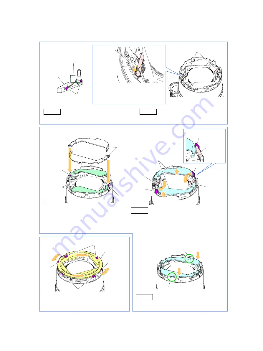
(1) Attach the BARRIER PLATE 3 and BARRIER PLATE SPRING 2 as shown in the figure below.
(2) Attach the BARRIER PLATE 1 as shown in the figure below.
(3) Attach the BARRIER CAP as shown in the figure below.
Slightly loosen the BARRIER PLATES 1,
and rotate the BARRIER PLATES 3 so
that the BARRIER PLATES 3 are
passed below either one of the
BARRIER PLATES 1 and placed
between one of the portions C and one
of the BARRIER PLATES 1.
Place the BARRIER CAP as shown in the
figure, rotate it and engage two dowels and
four claws A to attach the BARRIER CAP.
Push in the BARRIER PLATES 1 and
engage the ribs with the BARRIER
PLATES 2.
Note on Reassembling (2)
Note on Reassembling (1)
BARRIER PLATE
SPRING 2
BARRIER
PLATE 3
BARRIER PLATE 3
BARRIER
PLATE 3
BARRIER
PLATE 1
BARRIER
PLATE 2
BARRIER
PLATE 3
BARRIER
PLATE 3
Claw B
STEP 2
STEP 1 Attach the BARRIER PLATE SPRING 2
to the BARRIER PLATE 3.
STEP 1
Engage the BARRIER PLATE 1 in the
bosses of the BARRIER PLATE 2 to attach.
Insert the BARRIER PLATE 3 to
positions shown in the figure above
and set it.
STEP 2
STEP 3
Section C
Section C
Section C
Move
aside
Move aside
BARRIER CAP
Claw A
Claw A
Boss
Boss
BARRIER PLATE 1
Push in.
Push in.
Rib
Rib
Dowel
Dowel
Note on Reassembling (3)
BARRIER
PLATE
SPRING 2
Attach the BARRIER PLATE
SPRING 2 so that its end is
placed between the upstanding
walls.
Upstanding
walls
Содержание PowerShot G11
Страница 10: ...7 2 Exterior 2 1 Exterior Phots ...
Страница 11: ...8 2 2 6 view Diagram 48 3 76 2 3 00 112 1 4 41 1 90 Unit mm inch Nominal Dimensions ...
Страница 25: ...22 3 2 System Diagram ...
Страница 26: ...23 3 3 Functions Available in Each Shooting Mode ...
Страница 27: ...24 3 4 Menus 3 4 1 Shooting Menu ...


