background image

5-3

5-3

General Circuit Diagram > General Circuit Diagram(Finisher)

General Circuit Diagram > General Circuit Diagram(Finisher)

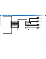
General Circuit Diagram(Finisher)

6

1

1

7

6

1

4

1

M

M

M

M

M

NC

NO

COM

NC

NO

COM

M

SL

SL

M

M

M

+24V

CN22

CN48

CN99

CN55

CN20

TO SST

TO OP-TRAY

TO SADDLE

TO ENGINE

+24V

STPSOL

SIMENSOL

PGND

F

AN2_LOCK

+24V

PGND

+24V

F

AN1_LOCK

+5V

1

2

3

CN18

1

2

3

CN17

CN18H

CN17H

4

3

2

1

CN15

CN15H

3

2

1

M9

3

2

1

M8

15

1 2 3 4

M7

13

14

12 11 10 9 8

2

3

4

6

1

5

7

CN37

1

2

CN39

+5V

+5V

+5V

SIMENS2

STPSLHPS

SGND

SGND

+5V

SIMENS1

SGND

+5V

SGND

GRPUHPS

SGND

STRYS

FCOVSW

STPSFSW

+24V1

+24V

STPM+

TR

YCLKS

+5V

TR

YFULS

+5V

TR

YEMPS

SGND

TR

YMOT

-

TR

YMOT+

SGND

FDS

SGND

*A

A

B

*B

+5V

GRPHP

SGND

*B

*A

A

B

*B

B

A

*B

B

A

*A

*A

*B

B

A

*A

+24V

RXD

SGND

R_BIT

SGND

D_ENABLE

CN96DH

2 3

1

CN96L

2

1

CN94D

3

1

2

CN96D

1 2 3 4

M6

1 2 3 4

M4

12

11

10

9

8

2 3 4 5 6

CN95D

CN95DH

13 12 11 10 9 8

2

3

4

5

7

CN52

1

7

11

10

9

8

2 3 4 5 6

CN8

2 1

CN60

2 1

CN34

CN94DH

2 1

CN94L

2 1

SOL2

2

SOL1

2

1

M10

4

3

2

1

CN12

CN12H

3

2

1

S7

1

2

3

S9

3

2

1

SW1

DE2L-AALB

3

2

1

SW2

DE2L-AALB

SOLD4

SOLD3

SOLD2

SOLD1

3

2

1

S14

1

4

3

2

CN16

2 3 4

1

CN4

CN16H

CN13H

MT3

1 2 3

S17

3 2 1

S19

1

2

3

S20

1

2

3

S18

1 2

M11

3

2

1

S11

3

2

1

S10

1 2 3

CN26D

1

2

3

CN19

3 2 1

S13

6

5

4

3

2

1

M3

1

2

3

4

5

6

7

8

9

10

11

CN3

1

2

3

4

5

6

7

8

9

10

11

CN47

1 2 3 4 5

CN40

MT1

MT2

3 4 5 6

1 2

CN11

3 4 5 6

1 2

CN10

2

1

6

5

4

3

CN14

1

3 2

CN44

2 3

1

CN45

MT4

2 3

1

CN46

1

3

2

CN51

2 3

1

CN56

2 1

CN100

2 1

CN54

11 10 9 8

2

3

4

5

7

CN53

5 4 3 2 1

CN2

4

1

2

3

CN42

1

4 3 2

CN1

2

3

CN97

12

11

10

9

8

2 3 4 5 6

1

7

CN49

2 3 4 5

1

CN50

3 4 5 6

1 2

CN38

1

3 2

CN31

2

3

1

CN32

8

1 2 3 4 5 6 7

CN98

15

14

13

12

11

10

9

8

2 3 4 5 6

1

7

CN35

1

2

CN43

4

3

2

1

M5

1 2 3 4 5 6

M1

6

5

4

3

2

1

M2

3 2 1

S5

3 2 1

S3

3 2 1

S1

3 2 1

S2

1

2

3

CN21

1

2

3

CN25

1

2

3

CN23

3

2

1

S6

3

2

1

S12

1 2 3

CN30

1 2 3

CN27

1 2 3

CN29

1 2 3

CN28

3

2

1

S16

1 2 3

S15

1 2 3 4

CN13

1 2 3 4 5 6 7

CN41

1

2

3

CN26L

CN26LH

1 2 3

CN96

MT5

MT6

12

8

1

11

2

3

4

5

6

7

9

10

CN95L

SGND

DF_RESET

SGND

D_MODE

TXD

SGND

PGND

*B

B

A

*A

*B

B

A

*A

+5V

SGND

GSCNCTS

+5V

SGND

SRSLMPS

+5V

SGND

SRNPS

FDROLS

+5V

+5V

SGND

SGND

TR

YMIDS

+5V

SGND

STPM+

STPM+

STPM-

STPM-

STPM-

+5V

STPHPS

STPSLFPS

STPEMPS

SGND

1

Feed Motor

STP Move Motor

Gripper Unit 

Move Motor

Entrance 

Roller 

Release / 

Stopper 

HP 

Motor

Shift 

Roller 

Release 

Motor

Shift Motor

Gripper 

Open / Close 

Motor

Front Fan

Motor

Rear Fan

Motor

Entrance 

Sensor

Shift Roller HP 

Sensor

Shift 

Roller 

Release 

Sensor

Entrance Roller 

Release / Stopper 

HP Sensor

Sensor 

Paper 

Lever 

Drive

Solenoid

Stapler

Solenoid

Sensor Processing 

Tray Sensor

Gripper Unit 

HP Sensor

Stapler Move 

HP Sensor

Finisher Controller PCB

Paper 

Surface

Sensor 2

Front Cover 

Switch

Paper Surface 

Sensor 

Stapler Safety Switch

Flexible Cable Broadcast PCB

Stapler 

Motor

Stapler HP 

Sensor

Stapler Edging 

Sensor

Stapler 

Sensor

Staple Unit

Stack 

Tray 

Clock 

Sensor

Stack

Tray

Middle 

Sensor

Tray Lift Motor

Stack Tray 

Lower Limit 

Sensor

Gripper 

Stapler 

Connection 

Sensor

Grip Arm 

Sensor

F-4-11

Содержание Perfect Binder D1

Страница 1: ...5 4 3 2 1 Inner Finisher D1 Inner Finisher Additional Tray A1 Service Manual Digest Rev0...

Страница 2: ...l information as the need arises In the event of major changes in the contents of this manual over a long or short period Canon will issue a new edition of this manual The following paragraph does not...

Страница 3: ...r switch closing the front door and closing the delivery unit door which results in supplying the machine with power 2 In the digital circuits 1 is used to indicate that the voltage level of a given s...

Страница 4: ...0 0 4...

Страница 5: ...3 Parts Placement Diagram List of Parts Finisher 3 2 Motors Switches Solenoids 3 2 Sensors1 3 2 Sensors2 3 3 PCBs 3 3 4 Product Outline Features Finisher 4 2 Specifications Finisher 4 3 Names of Part...

Страница 6: ...Safety Precautions Notes Before it Works Serving...

Страница 7: ...nnect the power plug CAUTION Do not turn off the power switch when downloading is under way Turning off the main power switch while downloading is under way can disable the machine CAUTION When perfor...

Страница 8: ...1 1 Periodic Servicing Periodic Service Works Finisher...

Страница 9: ...Category Part name Part number Qty Interval Remarks Adjusted not adjusted Reference 1 Stapler Stapler FM4 2710 1 CR 500 000 sheets None 2 Processing tray Offset Roller 4A3 1121 2 CR 1 000 000 sheets N...

Страница 10: ...2 2 Adjustment Basic Adjustment Adjustment at Time of Parts Replacement finisher...

Страница 11: ...ADJUST INSTP R1 50 to 50 0 1mm 0 Adjusting the 2 Staple Position When the middle 2 staple position is displaced Adjust the paper pull amount of the gripper at the middle 2 stapling position Incrementi...

Страница 12: ...counter value Select the item and then press Clear key To change the estimated life Select the item enter the value and then press OK key LV1 COPIER COUNTER DRBL 2 OFST RL 0 to 99999999 piece 0 Stapl...

Страница 13: ...g the Rear Staple Position LV1 SORTER ADJUST INSTP R1 Adjusting the 2 Staple Position LV1 SORTER ADJUST STP 2P Adjusting the Stapler Needle Pitch A4 LV1 SORTER ADJUST STP NTN Adjusting the switchback...

Страница 14: ...3 3 Parts Placement Diagram List of Parts Finisher...

Страница 15: ...ft motor SW1 Front cover switch SW2 Stapler safety switch SOL1 Paper lever drive solenoid SOL2 Stapler solenoid F 3 1 T 3 1 Sensors1 S5 S1 S2 S3 S17 S16 S14 S15 S6 S21 S23 S22 No Part name Part number...

Страница 16: ...ensor S10 Stapler move HP sensor S11 Paper surface sensor1 S12 Paper surface sensor2 S13 Gripper arm sensor S18 Stapler HP sensor S19 Stapler edging sensor S20 Stapler sensor F 3 3 T 3 3 PCBs PCB2 PCB...

Страница 17: ...4 4 Product Outline Features Finisher Specifications Finisher Names of Parts Finisher Basic Configuration Finisher...

Страница 18: ...4 4 2 Features Finisher A variety of finishing functions 2 delivery tray Multi stapling Large tray capacity 1000 sheets Utilize the inner room of the system...

Страница 19: ...heets L size 62 5mm high or less 62 5mm is equivalent to 500 sheets When the add tray A1 is installed Add tray A1 Upper tray S size 12 5mm high or less 12 5mm is equivalent to 100 sheets L size 12 5mm...

Страница 20: ...LGL LTR R 8K Plain paper 52 81 4g 30m2 30 sheets Plain paper more than 81 5g m2 105 0g m2 20 sheets Thick paper more than 106 0g m2 220g m2 2 sheets Staple replenishment Exclusive staple cartridge 50...

Страница 21: ...lerAdditional Tray A1 Stapler Stack extension tray 2 Stack extension tray 1 F 4 1 F 4 2 External View 3 Finisher front cover Cross Section 1 6 5 4 3 2 9 8 7 1 Stack tray 6 Stapler 2 Processing tray 7...

Страница 22: ...t roller Gripper Trailing edge aligning plate Stack tray Stack height detetion lever Ejection roller of the host machine Stapler Processing tray Switchback part Entrance roller Non sort stacking opera...

Страница 23: ...the double stapling side stitching 9 The shift roller moves down and gives higher pressure to the paper stack Gripper then opens and evacuates itself to the connecting position with the stapler Stack...

Страница 24: ...ft roller rotates to convey the paper stack until the trailing edge of the stack gets into the paper guide Returning to the connecting position Conveying direction Conveying the paper stack with the s...

Страница 25: ...5 5 General Circuit Diagram Service Tools General Circuit Diagram Finisher...

Страница 26: ...Composition Remarks 1 Alcohol Cleaning e g glass plastic rubber parts external covers Hydrocarbon fluorine family Alcohol Surface activating agent Water Do not bring near fire Procure locally Substit...

Страница 27: ...4 2 3 1 CN46 1 3 2 CN51 2 3 1 CN56 2 1 CN100 2 1 CN54 11 10 9 8 2 3 4 5 7 CN53 5 4 3 2 1 CN2 4 1 2 3 CN42 1 4 3 2 CN1 2 3 CN97 12 11 10 9 8 2 3 4 5 6 1 7 CN49 2 3 4 5 1 CN50 3 4 5 6 1 2 CN38 1 3 2 CN3...

Страница 28: ...24V1 PGND PGND TRYMOT TRYMOT TRY2CKS SGND 5V TRY2ES SGND TRT2FS 5V SGND 5V 1 2 M12 2 1 CN57 3 2 1 S23 14 13 12 11 8 1 2 3 4 5 6 7 9 1 0 CN55 13 12 11 8 1 2 3 4 5 6 7 9 1 0 CN7 3 2 1 S21 1 2 3 S22 2 3...

Отзывы:

Похожие инструкции для Perfect Binder D1