A. Outline
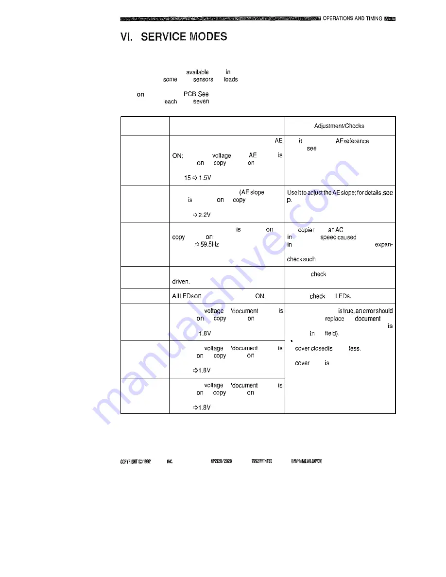
The service modes are
foruse adjust-
ing and checking
of the
and
and
can be activated by pressing the service switch
(SWI)
the adjustment
the table below
fordescriptionson
of the
service modes.
Service
mode No.
Description
0
The scanner movesforward to the pointof
Use to adjust the
point; for
measurement, and the scanning lamp goes
details,
p. 3-34.
the output
of the
sensor
indicated
the
counter
the control
panel.
EX.
1
The read-involtage of VR2
adjust-
ment) indicated
the
counteron the
3-35.
control panel.
EX. 22
2
The powerfrequencydata indicated
the
The
uses
motor; the variation
counter
the control panel.
its rotation
byfluctuations
EX. -05
the frequency can bring about
sionlcontraction of the image; use it to
problems.
3
The pre-exposure lamp and main motor are
Use it to
the operation of the lamp
and motor.
4
the control panel go
Use it to
the
5
The output
of
size 0’ Ifanyofthefollowing
indicated
the
counter
the control
be suspected;
the
size
panel.
detection mechanism (no adjustment
EX. 180
possible the
The value indicated with the copyboard
6
The output
of
size 1’
20 or
indicated
the
counter
the control
. The value indicated with the copyboard
panel.
open 30 or more.
EX. 18
7
The output
of
size 2’
indicated
the
counter
the control
panel.
EX. 18
CANON
CANON
RN.1 JAN.
IN JAPAN
d
3-55
Содержание NP-2020
Страница 5: ......
Страница 171: ...LL w I n t 0 m a 9zcr 9zcr ...
Страница 172: ...I I i I am w m h I I r l I I B m 0 4 u I m ll ...
Страница 178: ...STAL SERVICE MANUAL COPYAIGHT 0 1592 CANON INC CANON NP2l20 2020 KV 0 MAY 1990 PAINTEO IN JAPAN IMPRIME AU JAPON ...


