


Chapter 15
15-1
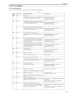
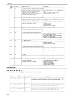
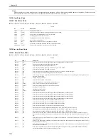
15.1 Error Code Details
15.1.1 Error Code Details
0013-1429
iR1020J / iR1024J / iR1020 / iR1024 / iR1024A / iR1024N / iR1024F / iR1024i / iR1024iF
T-15-1
Display
Code
Detail Code
Main Cause/Symptom
Countermeasure
E000
0000
Startup error
The temperature detected by the main or sub thermistor does
not rise to the specified value during startup control.
- Check the fixing film connector.
- Replace the fixing film unit.
- Replace the DC controller PCB.
E001
0000
Abnormally high temperature (detected by main thermistor)
The main thermistor detected an abnormally high temperature
(235 deg C) during temperature control.
- Check the connector of the fixing film unit.
- Replace the fixing film unit.
- Replace the DC controller PCB.
0001
Abnormally high temperature (detected by sub thermistor)
The sub thermistor detected an abnormally high temperature
(300 deg C) during temperature control.
- Check the connector of the fixing film unit.
- Replace the fixing film unit.
- Replace the DC controller PCB.
E002
0000
Low temperature during temperature control.
The target temperature is not reached during temperature
control.
- Check the connector of the fixing film unit.
- Replace the fixing film unit.
- Replace the DC controller PCB.
E003
0000
Abnormally low temperature (detected by main thermistor)
After the temperature detected by the main thermistor has
reached the specified value, it does not reach the specified
value during initial rotation.
- Check the connector of the fixing film unit.
- Replace the fixing film unit.
- Replace the DC controller PCB.
0001
Abnormally low temperature (detected by sub thermistor)
After the temperature detected by the sub thermistor has
reached the specified value, it does not reach the specified
value during initial rotation.
- Check the connector of the fixing film unit.
- Replace the fixing film unit.
- Replace the DC controller PCB.
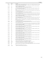
E010
0000
Main motor failure
The main motor is faulty.
- Check the connector of the main motor.
- Replace the main motor.
- Replace the DC controller PCB.
E019
0001
Waste toner full detection
The waste toner full state was detected.
Replace the drum unit
0002
Waster toner full detection sensor is faulty.
The waste toner full state was detected continuously for five or
more seconds while the main motor was turning.
- Check the connector of the waster toner full sensor.
- Replace the waste toner full sensor.
- Replace the DC controller PCB.
E100
0000
BD detection PCB failure
The BD detection PCB is faulty.
- Check the connector of the BD detection PCB.
- Replace the laser scanner unit.
- Replace the DC controller PCB.
E196
0001
Flash ROM write/read error
- Replace the image processor PCB.
The write/read of Flash ROM in the image processor PCB is
faulty.
0002
PCL ROM write/read error
- Replace the PCL PCB.
- Replace the image processor PCB.
The write/read of PCL ROM in the image processor PCB is
faulty.
E197
0000
Printer engine communication error
Erroneous communication between the DC controller PCB and
image processor PCB was detected.
- Check the connectors of the DC controller PCB and image
processor PCB.
- Replace the DC controller PCB for normal connection.
- Replace the image processor PCB.
E716
0000
Erroneous communication with optional cassette
Disconnection of the optional cassette was detected after
power-on, detection of normal connection to the optional
cassette, and start of communication.
- Check the connectors of the optional cassette PCB and DC
controller PCB.
- Replace the optional cassette PCB for normal connection.
- Replace the DC controller PCB.
Содержание iR1020 Series
Страница 1: ...Sep 1 2008 Service Manual iR1020 1021 1024 1025 Series ...
Страница 2: ......
Страница 6: ......
Страница 17: ...Chapter 1 Introduction ...
Страница 18: ......
Страница 20: ......
Страница 42: ...Chapter 1 1 22 The following warnings are given to comply with Safety Principles EN60950 F 1 16 F 1 17 ...
Страница 49: ...Chapter 1 1 29 ...
Страница 50: ......
Страница 51: ...Chapter 2 Installation ...
Страница 52: ......
Страница 54: ......
Страница 61: ...Chapter 2 2 7 ...
Страница 62: ......
Страница 63: ...Chapter 3 Basic Operation ...
Страница 64: ......
Страница 66: ......
Страница 73: ...Chapter 3 3 7 ...
Страница 74: ......
Страница 75: ...Chapter 4 Original Exposure System ...
Страница 76: ......
Страница 78: ......
Страница 87: ...Chapter 5 Laser Exposure ...
Страница 88: ......
Страница 90: ......
Страница 94: ......
Страница 95: ...Chapter 6 Image Formation ...
Страница 96: ......
Страница 98: ......
Страница 103: ...Chapter 7 Pickup Feeding System ...
Страница 104: ......
Страница 106: ......
Страница 120: ......
Страница 121: ...Chapter 8 Fixing System ...
Страница 122: ......
Страница 124: ......
Страница 135: ...Chapter 9 External and Controls ...
Страница 136: ......
Страница 138: ......
Страница 151: ...Chapter 10 Original Feeding System ...
Страница 152: ......
Страница 154: ......
Страница 156: ...Chapter 10 10 2 M2001 ADF motor Symbol Name ...
Страница 169: ...Chapter 10 10 15 2 Remove one connector 1 and one screw 2 and then remove the roller release solenoid 3 F 10 42 1 3 2 ...
Страница 170: ......
Страница 171: ...Chapter 11 e maintenance imageWARE Remote ...
Страница 172: ......
Страница 174: ......
Страница 184: ......
Страница 185: ...Chapter 12 Maintenance and Inspection ...
Страница 186: ......
Страница 188: ......
Страница 190: ......
Страница 191: ...Chapter 13 Standards and Adjustments ...
Страница 192: ......
Страница 194: ......
Страница 201: ...Chapter 14 Correcting Faulty Images ...
Страница 202: ......
Страница 204: ......
Страница 213: ...Chapter 14 14 9 F 14 6 ADF There is no circuit board in ADF 4 2 5 6 3 12 11 13 1 10 9 8 13 7 14 ...
Страница 214: ......
Страница 215: ...Chapter 15 Self Diagnosis ...
Страница 216: ......
Страница 218: ......
Страница 224: ......
Страница 225: ...Chapter 16 Service Mode ...
Страница 226: ......
Страница 230: ......
Страница 232: ...Chapter 16 16 2 Makes various status checks such as contact sensor sensor and print status ...
Страница 278: ......
Страница 279: ...Chapter 17 Upgrading ...
Страница 280: ......
Страница 282: ......
Страница 297: ...Chapter 18 Service Tools ...
Страница 298: ......
Страница 299: ...Contents Contents 18 1 Service Tools 18 1 18 1 1 Special Tools 18 1 ...
Страница 300: ......
Страница 302: ......
Страница 303: ...Sep 1 2008 ...
Страница 304: ......


