Chapter 13
13-1
13.1 Image Adjustments
13.1.1 Image parallelism adjustment
0014-5881
iR1020J / iR1024J / iR1020 / iR1024 / iR1024A / iR1024N / iR1024F /
iR1024i / iR1024iF
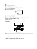
1) Create a test chart, load it in the ADF, and make a copy of it.
F-13-1
2) Compare the lines at the end of the test chart with those on the copy for
parallelism. Measure dimensions A and B at the end of the copy and ad-
just the amount of skew (the range shown in the table) to within the spec.
Standard: A-B within ±1.7 mm
F-13-2
<Adjustment method>
This machine allows parallelism between the leading and trailing edges of
the image to be adjusted by changing the positions where the front and rear
springs of the registration unit are hooked.
There are five types of spring hooking positions. (One step = Approx. 0.6
mm)
T-13-1
MEMO:
Parallelism varies depending on the difference in the spring pressure be-
tween the front and rear springs.
For example, the spring position "0"at the back of the host machine and the
spring position "-1"at the front of the host machine are not shown in this doc-
ument because they are the same as the spring position "+1"at the back of the
host machine and the spring position "0t the front of the host machine respec-
tively.
F-13-3
1) Check the current hooking positions of the left and right springs of the reg-
istration roller. Change the spring hooking positions in reference to the ta-
ble below. (They are adjustable in five steps. One step = Approx. 0.6 mm)
T-13-2
-If the A-side image (at the front of the host machine) is short (shrunken), re-
duce the setting value.
F-13-4
-If the B-side image (at the back of the host machine) is short (shrunken), in-
crease the setting value.
F-13-5
Settings
Spring positions at
the back of host
machine
Spring positions at
the front of host
machine
1
+1
-1
2
+1
0
3
0
0
4
-1
0
5
-1
1
Test Sheet
10mm
10mm
10mm
(feeding direction)
10mm
(feeding direction)
Test Sheet
A
B
Rear side
Front side
Settings
Spring
positions at
the back of
host machine
Spring positions
at the front of
host machine
Correction of image A
(The A-side extends.)
1
+1
-1
2
+1
0
3
0
0
4
-1
0
Correction of image B
(The B-side extends.)
5
-1
1
+1
+1
0
-1
0
-1
Front
Rear
(feeding direction)
A
B
A
B
(feeding direction)
Содержание iR1020 Series
Страница 1: ...Sep 1 2008 Service Manual iR1020 1021 1024 1025 Series ...
Страница 2: ......
Страница 6: ......
Страница 17: ...Chapter 1 Introduction ...
Страница 18: ......
Страница 20: ......
Страница 42: ...Chapter 1 1 22 The following warnings are given to comply with Safety Principles EN60950 F 1 16 F 1 17 ...
Страница 49: ...Chapter 1 1 29 ...
Страница 50: ......
Страница 51: ...Chapter 2 Installation ...
Страница 52: ......
Страница 54: ......
Страница 61: ...Chapter 2 2 7 ...
Страница 62: ......
Страница 63: ...Chapter 3 Basic Operation ...
Страница 64: ......
Страница 66: ......
Страница 73: ...Chapter 3 3 7 ...
Страница 74: ......
Страница 75: ...Chapter 4 Original Exposure System ...
Страница 76: ......
Страница 78: ......
Страница 87: ...Chapter 5 Laser Exposure ...
Страница 88: ......
Страница 90: ......
Страница 94: ......
Страница 95: ...Chapter 6 Image Formation ...
Страница 96: ......
Страница 98: ......
Страница 103: ...Chapter 7 Pickup Feeding System ...
Страница 104: ......
Страница 106: ......
Страница 120: ......
Страница 121: ...Chapter 8 Fixing System ...
Страница 122: ......
Страница 124: ......
Страница 135: ...Chapter 9 External and Controls ...
Страница 136: ......
Страница 138: ......
Страница 151: ...Chapter 10 Original Feeding System ...
Страница 152: ......
Страница 154: ......
Страница 156: ...Chapter 10 10 2 M2001 ADF motor Symbol Name ...
Страница 169: ...Chapter 10 10 15 2 Remove one connector 1 and one screw 2 and then remove the roller release solenoid 3 F 10 42 1 3 2 ...
Страница 170: ......
Страница 171: ...Chapter 11 e maintenance imageWARE Remote ...
Страница 172: ......
Страница 174: ......
Страница 184: ......
Страница 185: ...Chapter 12 Maintenance and Inspection ...
Страница 186: ......
Страница 188: ......
Страница 190: ......
Страница 191: ...Chapter 13 Standards and Adjustments ...
Страница 192: ......
Страница 194: ......
Страница 201: ...Chapter 14 Correcting Faulty Images ...
Страница 202: ......
Страница 204: ......
Страница 213: ...Chapter 14 14 9 F 14 6 ADF There is no circuit board in ADF 4 2 5 6 3 12 11 13 1 10 9 8 13 7 14 ...
Страница 214: ......
Страница 215: ...Chapter 15 Self Diagnosis ...
Страница 216: ......
Страница 218: ......
Страница 224: ......
Страница 225: ...Chapter 16 Service Mode ...
Страница 226: ......
Страница 230: ......
Страница 232: ...Chapter 16 16 2 Makes various status checks such as contact sensor sensor and print status ...
Страница 278: ......
Страница 279: ...Chapter 17 Upgrading ...
Страница 280: ......
Страница 282: ......
Страница 297: ...Chapter 18 Service Tools ...
Страница 298: ......
Страница 299: ...Contents Contents 18 1 Service Tools 18 1 18 1 1 Special Tools 18 1 ...
Страница 300: ......
Страница 302: ......
Страница 303: ...Sep 1 2008 ...
Страница 304: ......


