


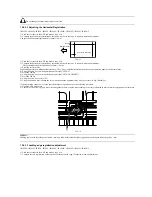


The specified end registration is 10mm +/-2mm.
F-13-13
The image is shifted to the left. -> Decrease the value.
The image is shifted to the right. -> Increase the value.
Unit of adjustment 1 = 0.1 mm
3) Enter the service mode.
Sequentially press the Additional functions key, 2 key, 8 key, and Additional functions key on the operation panel of the host machine.
4) Using the arrow keys on the operation panel, display "#SCAN".
5) Press the OK key.
6) Using the arrow keys on the operation panel, display "#SCAN NUMERIC".
7) Press the OK key.
8) Using the arrow keys, select "42".
9) Using the numeric keys, change the value to determine the optimum value. Next, press the OK key. (Default: 219)
If the registration cannot be set to the specified value using software, make adjustments again starting with the perpendicular adjustment.
Copy of the test sheet
(feeding direction)
Leading edge margin
L
Содержание iR1020 Series
Страница 1: ...Sep 1 2008 Service Manual iR1020 1021 1024 1025 Series ...
Страница 2: ......
Страница 6: ......
Страница 17: ...Chapter 1 Introduction ...
Страница 18: ......
Страница 20: ......
Страница 42: ...Chapter 1 1 22 The following warnings are given to comply with Safety Principles EN60950 F 1 16 F 1 17 ...
Страница 49: ...Chapter 1 1 29 ...
Страница 50: ......
Страница 51: ...Chapter 2 Installation ...
Страница 52: ......
Страница 54: ......
Страница 61: ...Chapter 2 2 7 ...
Страница 62: ......
Страница 63: ...Chapter 3 Basic Operation ...
Страница 64: ......
Страница 66: ......
Страница 73: ...Chapter 3 3 7 ...
Страница 74: ......
Страница 75: ...Chapter 4 Original Exposure System ...
Страница 76: ......
Страница 78: ......
Страница 87: ...Chapter 5 Laser Exposure ...
Страница 88: ......
Страница 90: ......
Страница 94: ......
Страница 95: ...Chapter 6 Image Formation ...
Страница 96: ......
Страница 98: ......
Страница 103: ...Chapter 7 Pickup Feeding System ...
Страница 104: ......
Страница 106: ......
Страница 120: ......
Страница 121: ...Chapter 8 Fixing System ...
Страница 122: ......
Страница 124: ......
Страница 135: ...Chapter 9 External and Controls ...
Страница 136: ......
Страница 138: ......
Страница 151: ...Chapter 10 Original Feeding System ...
Страница 152: ......
Страница 154: ......
Страница 156: ...Chapter 10 10 2 M2001 ADF motor Symbol Name ...
Страница 169: ...Chapter 10 10 15 2 Remove one connector 1 and one screw 2 and then remove the roller release solenoid 3 F 10 42 1 3 2 ...
Страница 170: ......
Страница 171: ...Chapter 11 e maintenance imageWARE Remote ...
Страница 172: ......
Страница 174: ......
Страница 184: ......
Страница 185: ...Chapter 12 Maintenance and Inspection ...
Страница 186: ......
Страница 188: ......
Страница 190: ......
Страница 191: ...Chapter 13 Standards and Adjustments ...
Страница 192: ......
Страница 194: ......
Страница 201: ...Chapter 14 Correcting Faulty Images ...
Страница 202: ......
Страница 204: ......
Страница 213: ...Chapter 14 14 9 F 14 6 ADF There is no circuit board in ADF 4 2 5 6 3 12 11 13 1 10 9 8 13 7 14 ...
Страница 214: ......
Страница 215: ...Chapter 15 Self Diagnosis ...
Страница 216: ......
Страница 218: ......
Страница 224: ......
Страница 225: ...Chapter 16 Service Mode ...
Страница 226: ......
Страница 230: ......
Страница 232: ...Chapter 16 16 2 Makes various status checks such as contact sensor sensor and print status ...
Страница 278: ......
Страница 279: ...Chapter 17 Upgrading ...
Страница 280: ......
Страница 282: ......
Страница 297: ...Chapter 18 Service Tools ...
Страница 298: ......
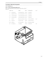
Страница 299: ...Contents Contents 18 1 Service Tools 18 1 18 1 1 Special Tools 18 1 ...
Страница 300: ......
Страница 302: ......
Страница 303: ...Sep 1 2008 ...
Страница 304: ......


