Chapter 2
2-36
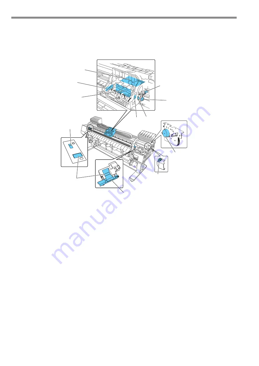
The multi sensor standard has a white plate attached to it, so that a reference value can be calculated during carriage height measurement by measuring the intensity
of light reflected upon the white plate.
(Service mode: SERVICE MODE>ADJUST>GAP CALIB)
h) Rail cleaner
The shaft cleaner located in the right rear of the carriage helps keep the main rail clean.
i) Internal unit temperature sensor
One thermistor is installed on the head relay PCB on the back of the head holder to detect the internal unit temperature.
F-2-18
T-2-10
[1]
Carriage relay PCB
[7]
Shaft cleaner
[2]
Multi sensor
[8]
Maintenance jet tray
[3]
Head relay PCB
[9]
Carriage HP sensor
[4]
Lift cam sensor
[10]
Multisensor reference
[5]
Sensor flag
[11]
Head management sensor unit
[6]
Lift cam
[12]
Lift motor
[1]
[2]
[3]
[4]
[5]
[6]
[7]
[8]
[9]
[10]
[11]
[12]
Содержание iPF9000 series
Страница 1: ...Aug 8 2007 Service Manual iPF9000 series ...
Страница 2: ......
Страница 6: ......
Страница 13: ...Chapter 1 PRODUCT DESCRIPTION ...
Страница 14: ......
Страница 25: ...Chapter 1 1 9 F 1 13 ...
Страница 92: ...Chapter 1 1 76 3 Push in the left and right Basket Rods toward the back all the way until they stop F 1 37 ...
Страница 102: ...Chapter 1 1 86 ...
Страница 103: ...Chapter 1 1 87 ...
Страница 104: ......
Страница 105: ...Chapter 2 TECHNICAL REFERENCE ...
Страница 106: ......
Страница 172: ......
Страница 173: ...Chapter 3 INSTALLATION ...
Страница 174: ......
Страница 176: ......
Страница 218: ...Chapter 3 3 42 F 3 85 6 FAN UNIT 7 FAN UNIT A ...
Страница 231: ...Chapter 3 3 55 F 3 107 6 FAN UNIT 7 FAN UNIT A ...
Страница 233: ...Chapter 3 3 57 ...
Страница 234: ......
Страница 235: ...Chapter 4 DISASSEMBLY REASSEMBLY ...
Страница 236: ......
Страница 238: ......
Страница 271: ...Chapter 4 4 33 5 Upper stay shaft hole 1 gear shaft 2 shaft end 3 gear cog face 4 F 4 55 1 2 4 3 ...
Страница 273: ...Chapter 4 4 35 ...
Страница 274: ......
Страница 275: ...Chapter 5 MAINTENANCE ...
Страница 276: ......
Страница 278: ......
Страница 285: ...Chapter 5 5 7 ...
Страница 286: ......
Страница 287: ...Chapter 6 TROUBLESHOOTING ...
Страница 288: ......
Страница 316: ...Chapter 6 6 26 49 GND GND 50 H1 B HE 2_B OUT Head L heat enable signal 2 B J3602 Pin Number Signal name IN OUT Function ...
Страница 354: ......
Страница 355: ...Chapter 7 SERVICE MODE ...
Страница 356: ......
Страница 358: ......
Страница 420: ......
Страница 421: ...Chapter 8 ERROR CODE ...
Страница 422: ......
Страница 424: ......
Страница 431: ...Aug 8 2007 ...
Страница 432: ......


