


Chapter 14
14-9
F-14-12
14.1.6 Checking the Surface Potential Control System
0015-5286
iR5065 / iR 5055 / iR5075 / / /
1. Outline
If an image fault occurs, it is necessary to find out whether the cause is in the static image formation block including the photosensitive drum and the potential
control system or if it is caused at time of development or transfer.
An image fault may be isolated by finding out whether the surface potential is correct using service mode.
2. Disabling the Auto Control Mechanisms
As a means of checking the potential control system, the auto control mechanism may be disabled (hereafter, non-auto control mode).
If the image fault in question is more or less corrected when the machine is in non-auto control mode, you can suspect the potential measurement unit and
the DC controller PCB as the cause of the fault.
You can also take advantage of non-auto control mode as a tentative remedy when the auto control mechanism has a fault.
When the machine is in non-auto control mode, all settings used for corona current control, laser power control, and developing bias control will be automatically
be set to default settings.
Using Non-Auto Control Mode
1) Make the following selections in service mode, enter '0', and press the OK key:
COPIER>OPTION>BODY>PO-CNT.
2) Press the Reset key twice.
3. Making a Zero-Level check
A "zero-level check" is a check made to see if the control mechanism of the DC controller PCB is identifying a 0-V level without fail when the drum surface
potential is 0 V.
A zero-level check may be made in either of 2 ways, and you can use it to decided whether the DC controller PCB and the potential measurement PCB is free
of error:
Method 1: use it to find out if the level shift circuit on the DC controller PCB is free of a fault
Method 2: use it to find out if the potential control circuit is free of a fault
(1) Method 1
1) Turn off the main power switch.
2) Remove the upper rear over.
3) Short GP33 on the DC controller PCB and GND using a cable equipped with an alligator clips or probes on both ends.
When shorting CP33 and GND, take full care to avoid contact between the clip/probe and the pattern of the PCB and other elements.
4) Remove the left cover (upper), delivery cover, and left cover (middle).
5) Remove the 5 screws [1], and detach the PCB cover [2].
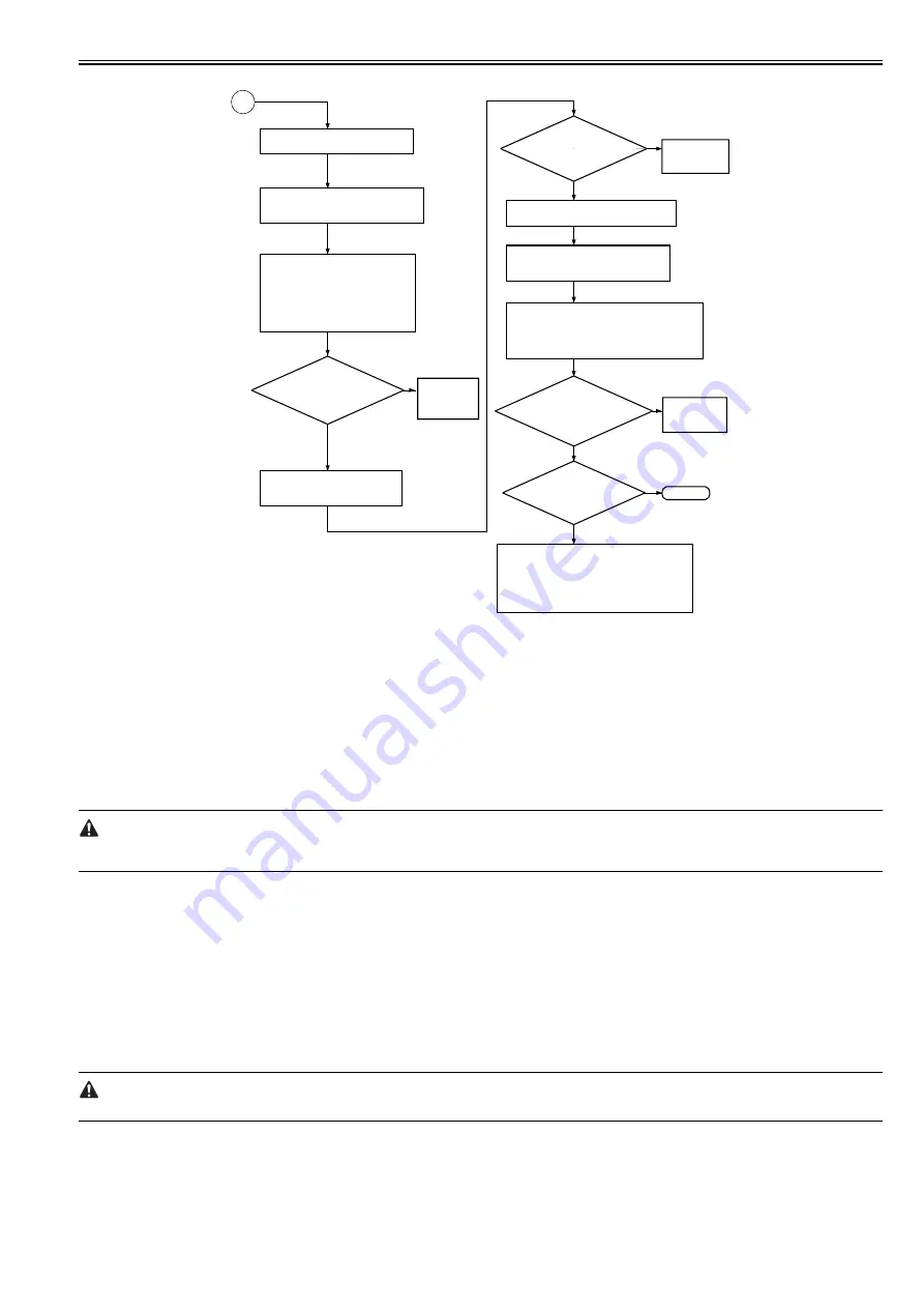
Check the developing assembly
for leakage; if normal, go to a
check on the transfer output.
Make the following selections (DC
value of the developing bias):
COPIER>DISPLAY>HV-STS>BIAS.
Covert the indication during printing
(V) into a control voltage with
reference to "Potential Control
Conversion Table."
Is the
deferense between
the actual measurement of
HVT_DEV-BIAS_DC and 'BIAS'
in service mode
± 10%?
YES
NO
Checking the Developing Bias Output
1) Check the transfer charging assembly for
leakage.
2) Make the following selections in service
mode, and try changing the setting:
COPIER>OPTION>BODY>FUZZY.
3) Try replacing paper.
Make the following selections in service mode
(level of current of transfer charging). Convert
the reading (mA) during printing into a control
voltage based on 8.5 "Potential Control
Conversion Table."
Replace the
photosensitive
drum.
NO
YES
NO
YES
NO
Is the
difference between
the measurement of HVT_
TRANSFER and 'TR' in
service mode
+/- 10%?
Checking the Transfer Output
Is the toner
image on the photosensitive
drum before transfer
normal?
Replace the
high-voltage transformer.
Is the problem
corrected?
YES
Replace the
DC controller
PCB.
Replace the
DC controller
PCB.
END
Enable potential control: COPIER>
OPTION>BODY>PO-CNT=1
B
Measure the voltage HVT_DEV_BIAS
_DC during printing of J102A-8 on the
DC controller PCB.
Disable the potential control mechanism
by setting '0' for the following:
COPIER>OPTION>BODY>PO-CNT.
Measure the voltage HVT_TRA during
printing of J102A-12 on the DC
controller PCB.
Содержание imageRUNNER 5055 series
Страница 1: ...Feb 26 2007 Service Manual iR5075 5065 5055 Series ...
Страница 2: ......
Страница 6: ......
Страница 27: ...Chapter 1 Introduction ...
Страница 28: ......
Страница 30: ......
Страница 52: ......
Страница 53: ...Chapter 2 Installation ...
Страница 54: ......
Страница 98: ...Chapter 2 2 42 ...
Страница 99: ...Chapter 3 Basic Operation ...
Страница 100: ......
Страница 102: ......
Страница 108: ......
Страница 109: ...Chapter 4 Main Controller ...
Страница 110: ......
Страница 112: ......
Страница 129: ...Chapter 5 Original Exposure System ...
Страница 130: ......
Страница 162: ......
Страница 163: ...Chapter 6 Laser Exposure ...
Страница 164: ......
Страница 166: ......
Страница 172: ......
Страница 173: ...Chapter 7 Image Formation ...
Страница 174: ......
Страница 178: ......
Страница 210: ......
Страница 211: ...Chapter 8 Pickup Feeding System ...
Страница 212: ......
Страница 263: ...Chapter 9 Fixing System ...
Страница 264: ......
Страница 268: ......
Страница 307: ...Chapter 10 External and Controls ...
Страница 308: ......
Страница 312: ......
Страница 321: ...Chapter 10 10 9 F 10 8 ...
Страница 345: ...Chapter 11 MEAP ...
Страница 346: ......
Страница 348: ......
Страница 389: ...Chapter 12 RDS ...
Страница 390: ......
Страница 392: ......
Страница 399: ...Chapter 13 Maintenance and Inspection ...
Страница 400: ......
Страница 402: ......
Страница 411: ...Chapter 14 Standards and Adjustments ...
Страница 412: ......
Страница 440: ......
Страница 441: ...Chapter 15 Correcting Faulty Images ...
Страница 442: ......
Страница 444: ......
Страница 470: ......
Страница 471: ...Chapter 16 Self Diagnosis ...
Страница 472: ......
Страница 474: ......
Страница 493: ...Chapter 17 Service Mode ...
Страница 494: ......
Страница 496: ......
Страница 552: ......
Страница 553: ...Chapter 18 Upgrading ...
Страница 554: ......
Страница 556: ......
Страница 572: ...Chapter 18 18 16 F 18 29 2 Click Start F 18 30 3 When the session has ended click OK ...
Страница 587: ...Chapter 18 18 31 F 18 59 2 Select the data to download F 18 60 3 Click Start ...
Страница 589: ...Chapter 19 Service Tools ...
Страница 590: ......
Страница 591: ...Contents Contents 19 1 Service Tools 19 1 19 1 1 List of Special Tools 19 1 19 1 2 List of Solvents Oils 19 1 ...
Страница 592: ......
Страница 595: ...Feb 26 2007 ...
Страница 596: ......


