


Introduction
The following rules apply throughout this Service Manual:
1. Each chapter contains sections explaining the purpose of specific functions and the relationship between electrical and mechanical systems with refer-
ence to the timing of operation.
In the diagrams,
represents the path of mechanical drive; where a signal name accompanies the symbol , the arrow
indicates the
direction of the electric signal.
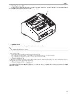
The expression "turn on the power" means flipping on the power switch, closing the front door, and closing the delivery unit door, which results in
supplying the machine with power.
2. In the digital circuits, '1'is used to indicate that the voltage level of a given signal is "High", while '0' is used to indicate "Low".(The voltage value, how-
ever, differs from circuit to circuit.) In addition, the asterisk (*) as in "DRMD*" indicates that the DRMD signal goes on when '0'.
In practically all cases, the internal mechanisms of a microprocessor cannot be checked in the field. Therefore, the operations of the microprocessors
used in the machines are not discussed: they are explained in terms of from sensors to the input of the DC controller PCB and from the output of the
DC controller PCB to the loads.
The descriptions in this Service Manual are subject to change without notice for product improvement or other purposes, and major changes will be com-
municated in the form of Service Information bulletins.
All service persons are expected to have a good understanding of the contents of this Service Manual and all relevant Service Information bulletins and be
able to identify and isolate faults in the machine."
Содержание FaxPhone L90
Страница 1: ...Feb 6 2008 Service Manual L90 L140 L160 L230 Series FAX L140 ...
Страница 2: ......
Страница 6: ......
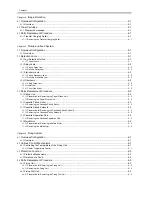
Страница 12: ...Contents ...
Страница 13: ...Chapter 1 Introduction ...
Страница 14: ......
Страница 16: ......
Страница 23: ...Chapter 2 Document Feed and Exposure System ...
Страница 24: ......
Страница 26: ......
Страница 33: ...Chapter 3 Laser Exposure ...
Страница 34: ......
Страница 36: ......
Страница 38: ......
Страница 39: ...Chapter 4 Image Formation ...
Страница 40: ......
Страница 42: ......
Страница 44: ......
Страница 45: ...Chapter 5 Pickup and Feed System ...
Страница 46: ......
Страница 48: ......
Страница 53: ...Chapter 6 Fixing System ...
Страница 54: ......
Страница 56: ......
Страница 61: ...Chapter 7 External and Controls ...
Страница 62: ......
Страница 72: ......
Страница 73: ...Chapter 8 Maintenance and Inspection ...
Страница 74: ......
Страница 76: ......
Страница 80: ......
Страница 81: ...Chapter 9 Measurement and Adjustments ...
Страница 82: ......
Страница 84: ......
Страница 87: ...Chapter 10 Correcting Faulty Images ...
Страница 88: ......
Страница 90: ......
Страница 93: ...Chapter 11 Error Code ...
Страница 94: ......
Страница 95: ...Contents Contents 11 1 Error Code 11 1 11 1 1 Error Code 11 1 ...
Страница 96: ......
Страница 100: ......
Страница 101: ...Chapter 12 Service Mode ...
Страница 102: ......
Страница 104: ......
Страница 121: ...Chapter 13 Service Tools ...
Страница 122: ......
Страница 123: ...Contents Contents 13 1 Service Tools 13 1 13 1 1 Solvent Oil List 13 1 ...
Страница 124: ......
Страница 126: ......
Страница 127: ...Feb 6 2008 ...
Страница 128: ......


