Chapter 2
2-1
2.1 Basic Construction
2.1.1 Outline of Electric Circuit
0010-3889
Electric circuits of this machine are controlled by the reader controller PCB and image processor PCB. The ASICs on the reader controller PCB and image processor
PCB detect the signals received from the host machine to output the signals that drive DC loads such as motors and solenoids at the predetermined timings. The
reader controller PCB and image processor PCB do not have a memory area; data (service mode, etc.) is stored in the image processor PCB.
F-2-1
2.2 Basic Operation
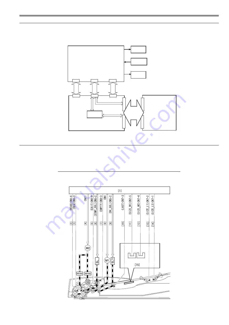
2.2.1 Drive Mechanism and Signals
0010-3892
This machine is a document feeder exclusively for stream reading.
This machine uses two motors to pick up and feed document paper.
T-2-1
The drive mechanism and signals are shown below.
F-2-2
Name (symbol)
Function
Feed motor (M1)
Feeds documents.
Pickup motor (M2)
Separates and feeds documents.
Motor
ADF driver PCB
Reader controller PCB
Solenoid
Sensor
+24V
ASIC(IC2)
Image
processor
PCB
J410
CN10
J412
CN1
+3.3V
J411
CN2
J403
J404
J308
J309
PI5
PI4
PI8
PI11
PI3
PI7
PI6
2
PI2
PI1
Содержание DADF-P1
Страница 1: ...Sep 14 2005 Service Manual Feeder DADF P1 ...
Страница 2: ......
Страница 6: ......
Страница 12: ......
Страница 13: ...Chapter 1 Specifications ...
Страница 14: ......
Страница 16: ......
Страница 19: ...Chapter 2 Functions ...
Страница 20: ......
Страница 22: ......
Страница 35: ...Chapter 3 Parts Replacement Procedure ...
Страница 36: ......
Страница 72: ......
Страница 73: ...Chapter 4 Maintenance ...
Страница 74: ......
Страница 76: ......
Страница 83: ...Chapter 5 Error Code ...
Страница 84: ......
Страница 86: ......
Страница 88: ......
Страница 89: ...Sep 14 2005 ...
Страница 90: ......


