


COPYRIGHT © 1998 CANON INC. CANON DADF-A1 REV.0 DEC. 1998 PRINTED IN JAPAN (IMPRIME AU JAPON)
2-45
CHAPTER 2 BASIC OPERATION
J. Controlling the Belt Motor
1. Outline
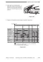
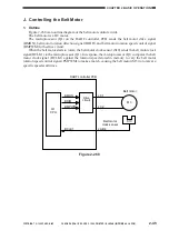
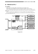
Figure 2-268 is an outline diagram of the belt motor control circuit.
The belt motor is a DC motor.
The microprocessor (Q1) on the DADF controller PCB sends the belt motor drive signal
(BMON), belt motor rotation direction signal (BDIR), and belt motor rotation speed control signal
(BMPWM) to the drive circuit.
When the belt motor starts to rotate, the belt motor clock sensor (S10) sends the belt motor clock
signal (BCLK1) to the microprocessor (Q1). In response, the microprocessor (Q1) compares the belt
motor clock signal (BCLK1) against the rotation speed stored in memory to vary the belt motor
rotation speed control signal (PMPWM) to make a match, causing the belt motor (M3) to rotate at a
specific speed at all times.
Figure 2-268
Belt motor
clock sensor
DADF controller PCB
Belt motor
Drive
circuit
J7-1
J7-2
J9-B4
S10
M3
Q1
CPU
BMON
BDIR
BMPWM
BCLK1


