


CHAPTER 5 TROUBLESHOOTING
5-28
COPYRIGHT © 1998 CANON INC. CANON DADF-A1 REV.0 DEC. 1998 PRINTED IN JAPAN (IMPRIME AU JAPON)
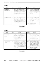
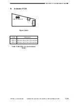
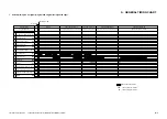
LED
Description
LED1
LED2
Use it when checking
the output of the origi
nal tray paper sensor.
Use it when checking
the output of the regi
stration sensor.
Table 5-401 LEDs on the DADF
Controller PCB
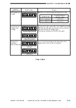
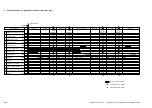
TP1-1
-2
-3
-4
-5
-6
Output of the original tray paper sensor
Output of the registration sensor
For factory
For factory
+5V
GND
Test pin No.
Checks
Table 5-402 Test Pins on the DADF
Controller PCB
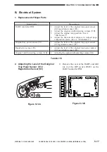
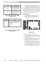
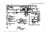
• Checking the Output of the Original Tray
Paper Sensor/Registration Sensor
If you have replaced the DADF controller
PCB, original tray paper sensor, or registration
sensor in the field, you must make sure that the
output of each sensor is correct. (The light-
emitting unit and the light-receiving unit of
these sensors are not of a single entity.)
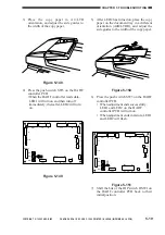
Making Checks
1) Turn off the copier's power switch.
2) Shift bit 4 of the DIP switch DSW on
the DADF controller PCB to on.
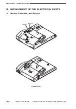
ON
12345678
LED1
LED2
SW1
TP1
J10
J15
J1
CB1
J2
J14
J12
J11
J7
J6
J13
J5
J9
J8
J3
6
1
B12
B1
2
1
1
3
1
2
1
3
1
2
13
1
14
2
A1
A12
1
1
1
1
9
10
1
4
2
2
8
1
7
1
DSW1
SW2
SW3
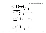
Figure 5-402
3) Turn on the copier's power switch.
4) With no original on the original tray, press
the push switch SW3 on the DADF
controller PCB once.
5) Check to make sure that LED1/LED2 on
the DADF controller PCB turn on, and the
voltage of TP2-1/TP2-2 is 1.1±0.1 V.
If the voltage of either TP2-1 or TP2-2 is
not as indicated, suspect displacement of
the light-emitting/-receiving unit of the
sensor corresponding to the probe of the
meter. Check the position of the sensor.


