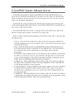
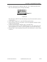
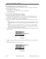
background image

COPYRIGHT© 2000 CANON INC.

 2000 2000 2000 

ColorPASS-Z40e/Z20e REV.0 AUG. 2000

CHAPTER 4 DISASSEMBLY/ASSEMBLY

4-25

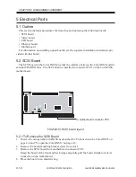
5.7.3 BIOS Chip

The BIOS chip is located in socket U8 on the motherboard. The BIOS chip contains boot

information, such as the startup diagnostics that the ColorPASS uses when you power on the
system.

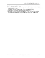
a. To Replace the BIOS Chip

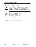
1. Locate the BIOS chip on the motherboard (socket U8).
2. Using a IC-removing tool, remove the BIOS chip from its socket on the motherboard.
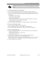
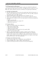
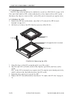
3. To replace the BIOS chip insert it into the socket so that the notch in the chip is aligned

with the notch in the socket.
Make sure to align the pins on the chip with the holes in the socket. If you notice any
bent pins, straighten them gently with a pair of needlenose pliers.

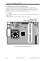
F04-507-04 Diagram of BIOS chip socket

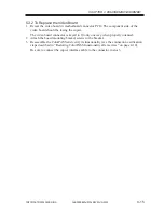
4. Reassemble the ColorPASS and verify its functionality (see “Restoring ColorPASS

functionality after service” on page 4-10).

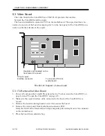
5.7.4 Motherboard battery

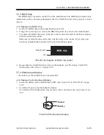
The battery on the motherboard is located at BT1.

a. To Replace the Motherboard Battery

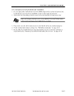
1. Locate the battery on the motherboard at BT1 (key location 15 in F04-506-01 on page

4-18).

2. Carefully lift up the clip that holds the battery.

Use caution when lifting up the clip; excessive force could cause the clip to lose its ten-
sion.

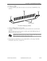
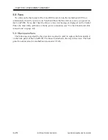
F04-507-05 Motherboard battery

BIOS chip

Socket notch

Pin 1

Clip

Socket

Battery

+

Содержание ColorPASS-Z20e

Страница 1: ...REVISION 0 FY8 13GW 000 COPYRIGHT 2000 CANON INC 2000 2000 2000 ColorPASS Z40e Z20e REV 0 AUG 2000 PRINTED IN JAPAN IMPRIME AU JAPON ColorPASS Z40e Z20e PS NX40W 20W AUG 2000 ...

Страница 2: ...anon will release technical information as the need arises In the event of major changes in the contents of this manual over a long or short period Canon will issue a new edition of this manual The following paragraph does not apply to any countries where such provisions are inconsistent with local law Trademarks The product names and company names used in this manual are the registered trademarks...

Страница 3: ...connection of the power plug from the electric outlet Indicates an item intended to provide notes assisting the understanding of the topic in question Memo Indicates an item of reference assisting the understanding of the topic in ques tion REF Provides a description of a service mode Provides a description of the nature of an error indication Refers to the Copier Basics Series for a better unders...

Страница 4: ... Started Job Management Guide Printing Guide Configuration Guide Color Guide for use by the user All service persons are encouraged to read these documents at least once to find out how the ColorPASS PS NX may be set up by making various optional settings The ColorPASS PS NX is a maintenance inspection free product The description in this Service Manual are subject to change without notice for pro...

Страница 5: ...rk Packet Exchange IPX are registered trademarks of Novell Inc Pentium Celeron are registered trademarks of Intel Corporation UNIX is a registered trademark of System Laboratories All brand names and product names used in this Service Manual are trademarks regis tered trademarks or trade names of their respective holders ...

Страница 6: ... Never dis turb the LAN by breaking or making a network connection altering termination install ing or removing networking hardware or software or shutting down networked devices without the knowledge and express permission of the system or network administrator or the shop supervisor 2 Never enter an IP address in ColorPASS Network Setup Only the network administrator should enter an IP address o...

Страница 7: ...c grounding strap grounded at the same place as the antistatic mat If that is not possible Attach a grounding strap to your wrist Attach the other end to a good ground When you unpack the ColorPASS from the carton for the first time touch a metal area of the copier to discharge the static on your body Before you remove the ColorPASS side panel and before you handle internal compo nents touch a met...

Страница 8: ... Installing the ColorPASS on the copier 2 10 1 5 1 To Connect a Twisted Pair Cable to the ColorPASS 3 7 2 Control Panel 3 8 2 1 Using the Control Panel 3 8 2 1 1 Activity Light 3 9 2 1 2 Buttons 3 9 2 2 Control Panel Screens and Icons 3 10 2 3 Functions Menu 3 12 3 Shutting Down and Restarting the ColorPASS 3 14 3 1 To Shut Down the ColorPASS 3 14 3 2 To Restart the ColorPASS 3 14 1 Installation 3...

Страница 9: ...o Board 4 14 5 3 1 To Remove the Video Board 4 14 5 3 2 To Replace the Video Board 4 15 5 4 UIB Board 4 16 5 4 1 To Remove the UIB Board 4 16 5 4 2 To Replace the UIB Board 4 16 5 5 Ethernet board 4 17 5 5 1 To Remove the Ethernet Board 4 17 5 5 2 To Replace the Ethernet Board 4 17 5 6 Motherboard 4 18 5 6 1 Removing the ColorPASS motherboard 4 18 5 6 2 Replacing the mother board 4 20 5 7 Replacin...

Страница 10: ...s 5 6 2 Checking the ColorPASS as a Stand alone Unit 5 8 2 1 To Isolate the ColorPASS 5 8 2 2 Errors and Beep Codes during Startup Diagnostics 5 8 1 Specifications A 1 2 3 General ColorPASS system error conditions 5 11 3 Checking the Entire ColorPASS System 5 13 3 1 Checking the Copier Interface 5 13 3 1 1 Printing the ColorPASS Test Page 5 13 3 1 2 Checking Scanning and Printing 5 14 3 2 Checking...

Страница 11: ...COPYRIGHT 2000 CANON INC 2000 2000 2000 ColorPASS Z40e Z20e REV 0 AUG 2000 CHAPTER 1 INTRODUCTION ...

Страница 12: ......

Страница 13: ...print jobs and select a printing priority for each job Users can control spooled print jobs sent to the ColorPASS with remote user software running on networked PC and Mac OS computers Print files in color grayscale and black and white Use the copier as a high resolution color scanner with Fiery Scan software Use 136 resident PostScript fonts 126 Adobe Type 1 PostScript and 10 TrueType plus two Ad...

Страница 14: ... includes a 433MHz CPU chip which controls the image data transfer to and from the video board and runs the interpreter The interpreter rasterizes the page de scription file and then compresses the image pattern into memory using compression tech nology The interpreter outputs compressed raster data through the image frame buffer memory to the ColorPASS video board The video board decompresses the...

Страница 15: ...created In addition the ColorPASS offers an efficient way to print files that have been saved in PostScript EPS Encapsulated PostScript or PDF Por table Document Format These files can be downloaded directly to the ColorPASS using Fiery Downloader one of the remote utilities for use with the ColorPASS Networked computers Network interface Ethernet board SCSI board HDD External Devices SCSI CD ROM ...

Страница 16: ...cation in which they were created Fiery Downloader also enables users to manage the printer fonts installed on the ColorPASS Enables users to view the order and priority of print jobs customize printer settings for jobs delete jobs and move jobs between queues It can also be used to view job accounting information ICC open color management and calibration tools enables users to edit and download I...

Страница 17: ...COPYRIGHT 2000 CANON INC 2000 2000 2000 ColorPASS Z40e Z20e REV 0 AUG 2000 CHAPTER 2 PREPARING FOR INSTALLATION ...

Страница 18: ......

Страница 19: ...sequence described in this chapter is designed to make your job as easy as possible Installation problems are easier to avoid and diagnose if you proceed from the component to the system level and verify functionality at each stage F02 100 01 on page 2 2 outlines the recommended installation procedure for connecting the ColorPASS to the copier Because the ColorPASS is a node on the customer s comp...

Страница 20: ...3 3 Print a ColorPASS Test Page page 3 4 Perform Test Scan print page 3 5 Verify network operation without the ColorPASS connected Network administrator connects the ColorPASS to the network and verifies the connection see page 3 8 and the Configuration Guide Network administrator configures Setup options see the Configuration Guide Network administrator installs ColorPASS user software on network...

Страница 21: ...e panel of the ColorPASS see the following illustration You may need to move the copier out from the wall for easier access to the connectors F02 201 01 Does the copier require service or adjustments Copy the copier color test page before you install the ColorPASS If the copied image indicates that the copier needs adjustment inform the customer After getting approval complete the copier service n...

Страница 22: ...e I F switching T02 201 01 3 Select settings for service mode For details see the copier Service Manual a ADJUST PASCAL MD Specify whether the gradation should be smoothed for output form the ColorPASS 0 Do not change 1 Do not use 2 Smooth gradation However copying speed will be lower by 0 5 sec b OPTION REMOTE Set it to suit the preference of the user c OPTION IPU TYPE Set it to 00 d OPTION FIL T...

Страница 23: ...d network requirements as specified in Getting Started 2 4 System Contact Person Will the person responsible for the computers and the network be available at the time set for installation Get a name as a contact 2 5 Setting Customer Expectations If the site is ready installation takes about one hour The customer should be informed of the following Some nodes on the network may be unavailable for ...

Страница 24: ...ide covers ColorPASS hardware installation and service It provides general information on connecting the ColorPASS to the customer s net work Network setup and configuration information goes beyond the scope of this guide For network setup and configuration information the network administrator should use the Configuration Guide ...

Страница 25: ... top container Inspect the contents for visible damage The top container should include the following items Bags containing a copier interface cable and an AC power cable Media package includes a package of user documentation and software 3 Give the media package to the customer or the network administrator Let the customer or network administrator know that in order to take full advantage of the ...

Страница 26: ... CANON INC 2000 2000 2000 ColorPASS Z40e Z20e REV 0 AUG 2000 CHAPTER 2 PREPARING FOR INSTALLATION 2 8 F02 301 01 Contents of ColorPASS shipping box ColorPASS Media Package ColorPASS power cable Copier interface cable ...

Страница 27: ...efore you install it F02 302 01 Front and back panels Top panel Activity light Up button Menu button Down button Line selection buttons Side panel Power switch Power connector Back panel Mouse connector not used Keyboard connector not used USB connectors not used Serial connector not used Serial connector not used Parallel connector not used Parallel connector not used SCSI connector CD ROM Copier...

Страница 28: ... Installing the ColorPASS on the copier 1 Remove the three face plates from the edge of the main copier unit as shown in F02 400 01 CLC1100 series The CLC900 series copier remove only two face plates F02 400 01 Removing face plates from copier 2 Detach the five stickers shown in F02 400 02 F02 400 02 Sticker locations ...

Страница 29: ...s on the copier top edge as shown in F02 400 03 F02 400 03 Inserting ColorPASS bosses 4 Mount the ColorPASS to the copier with three screws M4 6 CLC1100 series Attach the face plates round to the ColorPASS after fixing the unit in place The CLC900 series copier requires only two screws for ColorPASS installation F02 400 04 Installing ColorPASS mounting screws ...

Страница 30: ...the holes on the supports of the ColorPASS as shown in the following illustration Tighten the screws Upper side three places TP screws M4 10 Lower side two places RS tightening screws M4 33 F02 400 05 Inserting screws into ColorPASS supports 6 Fix the power cable in place to the ColorPASS using three cable clamps F02 400 06 Fix the power cable ...

Страница 31: ...COPYRIGHT 2000 CANON INC 2000 2000 2000 ColorPASS Z40e Z20e REV 0 AUG 2000 CHAPTER 3 INSTALLATION ...

Страница 32: ......

Страница 33: ...up to check the ColorPASS for internal problems The following procedure describes how to connect power to the ColorPASS 1 1 1 To Connect Power and Start the ColorPASS 1 Connect the recessed end of the ColorPASS power cable to the power connector at the side of the ColorPASS see F03 101 01 2 Make sure the ColorPASS power switch is in the off position press 0 and then connect the other end of the Co...

Страница 34: ...erating properly allow ColorPASS startup to pro ceed without interruption while you watch the Control Panel Do not press any buttons on the Control Panel 5 Allow the system to proceed to Idle to confirm that the ColorPASS is operating cor rectly The message Check power and cable may display in the Control Panel during the startup process Once the ColorPASS is connected to the copier the message sh...

Страница 35: ...ColorPASS To the Copier 1 Power off the ColorPASS and the copier You may need to get permission from the network administrator or supervisor to power off the copier 2 Locate the ColorPASS copier interface cable and connect the cable to the interface port on the copier Tighten the screws completely 3 Connect the other end of the cable to the ColorPASS copier interface connector in slot 3 on the bac...

Страница 36: ...Panel as the ColorPASS runs through its startup diag nostics 3 Before proceeding make sure that the copier is not in use The ColorPASS Info screen should read Idle 4 At the Idle screen press the menu button once see Using the Control Panel on page 3 8 The Functions menu is shown below F03 103 01 5 Press the line selection button to the right of Print Pages and then select Test Page The ColorPASS s...

Страница 37: ... Place the document that you want to scan on the copier glass 2 At the Idle screen press the menu button once to display the Functions menu F03 103 02 3 Select Run Diagnostics from the Functions menu 4 At the Diagnostics screen select Test Scan Print The message Scanning from copier and printing is displayed F03 103 03 5 When the ColorPASS is finished printing compare the output from the copier to...

Страница 38: ...o pinpoint the cause of problems should they occur 1 5 Connecting to the Network ColorPASS network support is provided through the Ethernet board The Ethernet board10 100BaseT connector is located at slot 6 on the back panel Supported Ethernet board cabling includes 10 100BaseT unshielded twisted pair For additional network infor mation see the Configuration Guide Token Ring compatibility is avail...

Страница 39: ...100BaseT 3 Configure Setup options It is the network administrator s responsibility to configure Setup according to the net work and user environment Refer the network administrator to the Configuration Guide for Setup information 4 After configuring Setup options verify the network connection Once the network connection has been made and the ColorPASS has the correct Setup configuration the Color...

Страница 40: ...Panel to ac cess and monitor different functions of the ColorPASS The current status of the ColorPASS and Setup information are displayed in the ColorPASS display window ColorPASS activity can be monitored in the display window and functions of the ColorPASS such as printing a Test Page and installing or updating system software can be controlled using the buttons on the Control Panel F03 201 01 T...

Страница 41: ... The ColorPASS is powered off Line selection buttons There are four line selection buttons on the right side of the Control Panel Use these buttons to select the command dis played on the corresponding line of the display window A special character appears in the display window next to a button when it is available Up and down buttons Use these buttons to scroll to different screens in multi scree...

Страница 42: ...ne of the screen displays the name of the current screen with the icon for that screen highlighted Icons for other active screens are also displayed but are not high lighted The ColorPASS screens display the following information F03 202 01 Control Panel screens during printing If an error occurs the Alert screen is displayed with a message describing the error F03 202 02 Cancel Job Jane D Copies ...

Страница 43: ...f the document currently processing User name The name of the user who sent the job that is currently be ing processed Kilobytes The amount in kilobytes of the job that has been processed so far Info Status The Info Status screen displays information about the server s current activity and software version This screen is always active and it ap pears in the display window when no other screen is s...

Страница 44: ...y options installed on the ColorPASS Job Log Prints the log of the last 55 jobs by default For more information about the job log see the Printing Guide Control Panel Map Prints the Setup screen help pages These pages are useful when navigating through the different Setup screens Color Charts Prints the color reference charts These pages include swatches of the RGB CMY and PANTONE colors available...

Страница 45: ...p is required the first time the copier is powered on and after ColorPASS system software is installed You must save changes to Server Network and Printer Setup after installing system software See the Configuration Guide for a list of options and detailed descriptions of each Setup option Run Diagnostics When you select this option you can choose from the following Test Scan Print Scans whatever ...

Страница 46: ...n the ColorPASS is finished processing the job 2 At the Idle screen press the menu button once to display the Functions menu F03 301 01 3 Select Shut Down from the Functions menu At the next screen select Shut Down Sys tem The message It is now safe to power off the system is displayed 4 Power off the ColorPASS using the power switch on the side panel press 0 3 2 To Restart the ColorPASS 1 If the ...

Страница 47: ...COPYRIGHT 2000 CANON INC 2000 2000 2000 ColorPASS Z40e Z20e REV 0 AUG 2000 CHAPTER 4 DISASSEMBLY ASSEMBLY ...

Страница 48: ......

Страница 49: ...the same screws for any particular location 1 2 Shut Down the ColorPASS Shut down the ColorPASS abruptly can disrupt the function of the network Be sure to obtain the consent of the network supervisor before shut down it 1 3 Handling the Parts The components of the printer board unit are susceptible to static electricity Be sure to wear a wrist strap designed for discharging static electricity whe...

Страница 50: ... fan CPU fan Power supply HDD hard disk drive SeeF04 202 01 on page 4 3 for an overview of components Replacement parts are avail able from your authorized service representative When performing the service procedures described in this chapter follow the precautions listed in Precautions on page vii 2 2 System Software Service ColorPASS system software is installed on the HDD at the factory A back...

Страница 51: ...02 01 Exploded view of ColorPASS components 2 3 4 5 6 8 1 9 14 15 10 11 12 13 7 Key 1 UIB cable 2 Tray 3 HDD cable 4 HDD 5 Power supply 6 Power supply cable 7 Back panel fans and fan cables 8 Motherboard 9 CPU fan CPU fan cable 10 Ethernet board 11 UIB board 12 Video board 13 SCSI board 14 Access panel 15 Top panel ...

Страница 52: ... to the ColorPASS a To shut down the ColorPASS 1 Make sure that the ColorPASS Info screen reads Idle When Printing or Ripping appears on the Control Panel the ColorPASS is currently pro cessing Idle appears in the Info screen when the ColorPASS is finished processing the job 2 At the Idle screen press the menu button once to display the Functions menu F04 203 01 3 Select Shut Down from the Functio...

Страница 53: ...e of the ColorPASS 3 Pull back the two clips beneach the front edge of the ColorPASS to release the front of the top panel see F04 301 01 on page 4 5 4 Push the top panel toward the back panel so that the three hooks on the back edge of the top panel release from the chassis F04 301 01 Removing the ColorPASS top panel 5 Disconnect the UIB cable from the top panel 6 Remove the access panel from the...

Страница 54: ...dard board configuration as shown in F04 301 02 on page 4 6 If optional components have been installed see the documentation that came with the specific kit F04 301 02 ColorPASS motherboard and back panel view Motherboard connectors AGP1 Empty PCI1 SCSI board PCI2 Video board PCI3 UIB board PCI4 Empty optional Token Ring board PCI5 Ethernet board ISA1 Empty ISA2 Empty Top view Back panel view Slot...

Страница 55: ...ed Looking into the tray from the top the standard board configuration includes the follow ing from right to left Connector AGP1 Empty Connector PCI1 SCSI board Connector PCI2 Video board Connector PCI3 UIB board Connector PCI4 Empty optional Token Ring board Connector PCI5 Ethernet board Connector ISA1 Empty Connector ISA2 Empty 2 Inspect ribbon cables to see if they are intact Faulty ribbon cabl...

Страница 56: ...le Key 1 Power supply cable 2 HDD cable 3 CPU fan cable 4 UIB cable 5 Back panel fan cable From Power supply Motherboard connector PIDE CPU fan UIB in the top panel Back panel fans To a Motherboard b HDD HDD IDE master Motherboard connector CPU FAN Connector J4 on the UIB board Fan connector on the motherboard CFAN Power supply HDD 1a 1b 2 3 4 5 5 Motherboard ...

Страница 57: ...nd 2 To release a DIMM push outward on the levers on each side of the DIMM F04 402 01 Releasing the DIMM levers 3 Slide the DIMM straight out of the socket 4 To replace a DIMM gently slide the DIMM straight into the socket until the levers at each side lock into place Make sure that the levers close securely around the ends of the DIMM and that each DIMM is fully seated in its socket If you remove...

Страница 58: ...to damage any ribbon cables if necessary fold the ribbon cables inside the tray before replacing the access panel 4 Insert the three hooks on the back edge of the top panel into the three slots at the back of the tray 5 Press the two clips at the front of the top panel into the two slots at the front of the tray 6 Attach the screw beneach the front edge of the ColorPASS F04 403 01 Replacing the to...

Страница 59: ... as outlined in F04 403 02 F04 403 02 ColorPASS connection verification steps Power up and check startup See To connect power and start the ColorPASS on page 3 1 Connect the ColorPASS to the copier See Connecting to the copier on page 3 3 Connect the ColorPASS to the network See Connecting to the network on page 3 6 and the Check the Setup options See the Configuration Guide Print the ColorPASS Te...

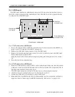
Страница 60: ... PASS provides the interface between the ColorPASS and the external CD ROM drive The SCSI board is installed in connector PCI1 on the ColorPASS motherboard F04 502 01 SCSI board layout 5 2 1 To Remove the SCSI Board 1 Power off and open the ColorPASS as described in To shut down the ColorPASS on page 4 4 and To open the ColorPASS on page 4 5 2 Remove the board mounting bracket screw from slot 1 3 ...

Страница 61: ...d connectorPCI1 The component side of the board should be facing the copier The board connector is keyed to fit only one way when properly oriented 2 Attach the board mounting bracket screw to the bracket in slot 2 3 Reassemble the ColorPASS and verify its functionality see the connection verification steps described in Restoring ColorPASS functionality after service on page 4 10 ...

Страница 62: ...agram of video board 5 3 1 To Remove the Video Board 1 Power off and open the ColorPASS as described in To shut down the ColorPASS on page 4 4 and To open the ColorPASS on page 4 5 2 Make sure the copier interface cable connected to the back of the ColorPASS is re moved 3 Remove the board mounting bracket screw that secures the board 4 Remove the video board from motherboard connector PCI2 Grasp t...

Страница 63: ... the video board should be facing the copier The video board connector is keyed to fit only one way when properly oriented 2 Attach the board mounting bracket screws to the bracket 3 Reassemble the ColorPASS and verify its functionality see the connection verification steps described in Restoring ColorPASS functionality after service on page 4 10 Be sure to connect the copier interface cable to th...

Страница 64: ...rom motherboard connector PCI3 Grasp the board at the front and back edge and gently pull it straight out of its connec tor 4 Place the board in an antistatic bag 5 4 2 To Replace the UIB Board 1 Reseat the UIB board in connector PCI3 on the motherboard Make sure that the parallel connector on the board extends through slot 4 in the back panel The component side of the UIB board should be facing t...

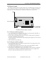
Страница 65: ...t screw from slot 6 and then remove the Ethernet board from motherboard connector PCI5 Grasp the board at the front and back edge and gently pull it straight out of its connector on the motherboard 3 Place the board in an antistatic bag 5 5 2 To Replace the Ethernet Board 1 Insert the Ethernet board into motherboard connector PCI5 The component side of the board should be facing the copier The Eth...

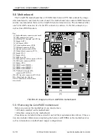
Страница 66: ...herboard Procedures are included in this section for each of the requirements listed above This sec tion also includes information on replacing the battery and DIMMs on the motherboard as well as information on motherboard jumper configurations 1 2 3 4 5 6 7 8 9 11 10 MS MS MS MS MS MS 12 13 16 15 16 17 18 19 20 Key 1 Keyboard mouse connectors not used 2 USB connector not used 3 433MHz CPU heatsin...

Страница 67: ...nector PCI4 if installed Ethernet board in connector PCI5 4 Remove any option boards installed in remaining connectors on the motherboard b To Remove Motherboard Cables 1 Remove the power supply cable from PWR CON 2 Remove the HDD cable from connector PIDE on the motherboard 3 Remove the back panel fan cable from connector CFAN on the motherboard c To Remove the Motherboard 1 If you are replacing ...

Страница 68: ...he motherboard with a new board replace the following components on the board Memory see page 4 25 CPU heatsink and CPU fan see page 4 26 BIOS chip see page 4 27 b To Replace Boards 1 Replace the following boards in the motherboard SCSI board in connector PCI1 Video board in connector PCI2 UIB board in connector PCI3 If the Token Ring board is installed reseat it in connector PCI4 Ethernet board i...

Страница 69: ... the board mounting bracket screws for boards installed in back panel slots Memo Make sure unused slots have slot covers installed Uncovered slots reduce air flow and could cause the ColorPASS to overheat 3 Press down on each cable connector and verify that all cables are attached properly 4 Check motherboard jumper settings See Motherboard jumpers on page 4 29 5 Reassemble the ColorPASS and verif...

Страница 70: ...rboard Before performing any of these procedures you must first power off the ColorPASS as described in To shut down the ColorPASS on page 4 4 and remove the side panel as described in To open the ColorPASS on page 4 5 5 7 1 DIMMs The ColorPASS motherboard has three DIMM sockets DIMM1 DIMM2 DIMM3 with 128MB installed Approved DIMMs are available from your service representative F04 507 01 Motherbo...

Страница 71: ...o replace a DIMM slide it straight into the socket until the levers on each side lock into place Make sure that the levers close securely around the ends of the DIMM and that each DIMM is fully seated in its socket Memo DIMMs fit the socket only one way The two notches on the bottom of each DIMM should line up with the notches in the socket 4 Reassemble the ColorPASS and verify its functionality s...

Страница 72: ... as described in To remove the CPU fan and heatsink on page 4 32 2 Lift the lever to release the CPU from the socket see F04 507 03 F04 507 03 Removing the CPU 3 Grasp the edges of the CPU and gently pull it out of the socket 4 Insert the new CPU so that the notch on the chip lines up with the notch area on the socket Pin 1 on the CPU is denoted by an angled corner The angled corner should point t...

Страница 73: ...th the notch in the socket Make sure to align the pins on the chip with the holes in the socket If you notice any bent pins straighten them gently with a pair of needlenose pliers F04 507 04 Diagram of BIOS chip socket 4 Reassemble the ColorPASS and verify its functionality see Restoring ColorPASS functionality after service on page 4 10 5 7 4 Motherboard battery The battery on the motherboard is ...

Страница 74: ...diagnostics complete then power off and on again to reinitialize the realtime clock 6 Reassemble the ColorPASS and verify its functionality see Restoring ColorPASS functionality after service on page 4 10 7 Configure the time and date in Setup When replacing the motherboard battery be sure to use the following items CR2032 Replace the motherboard battery only with the one listed in the Parts Cata ...

Страница 75: ...ed on pins 1 and 2 JP2 Clear CMOS and reset password Jumper installed on pins 1 and 2 during normal opera tion To reset the CMOS to the BIOS defaults move the jumper to pins 2 and 3 reboot and then replace jumper to pins 1 and 2 JP10 CPU speed settings Jumper installed on pins 1 and 2 This setting should not be changed JP11 CPU speed settings Jumper installed on pins 1 and 2 This setting should no...

Страница 76: ...as you power on the ColorPASS If you don t hear the fans or a fan error message is displayed on the Control Panel the most likely problem is a faulty power connection see To check board and cable connections on page 4 9 5 8 1 Back panel fans The following steps describe the procedure required in order to replace the fans installed on the back panel of the ColorPASS The fans are attached to the tra...

Страница 77: ... mounting screws on each fan and remove the fans from the tray F04 508 01 Removing the fans b To Replace the Back Panel Fans 1 Insert the new fans in the same locations and orientations at the old fans An arrow on the side of the fan indicates the airflow direction Make sure the fan is posi tioned so that the arrow points toward the back panel 2 Plug the 3 pin fan connectors into motherboard conne...

Страница 78: ...sink 1 Remove the CPU fan cable from motherboard connector CPU FAN 2 Shift down the clip of the CPU fan toward the CPU fan to remove the CPU fan 3 Lift the fan and heatsink assembly away from the CPU b To Replace the CPU Fan 1 Align the CPU fan with the heatsink 2 Hook the clip of the CPU fan on the claw of the base and secure the CPU fan to the motherboard 3 Reattach the CPU fan cable to motherbo...

Страница 79: ... supply not on the board or component connectors T04 509 01 describes the ColorPASS power connectors T04 509 01 ColorPASS power connectors Connector Pins Color Voltage 1 2 11 Green 3 3V 3 5 7 13 15 16 17 Black common 18 White 5V not connected 4 6 19 20 Red 5V 10 Yellow 12V 12 Blue 12V 14 not connected 8 Supply Power OK 9 Red 5VSB 1 Yellow 12V 2 Black common 3 Black common 4 Red 5V 1 Yellow 12V 2 B...

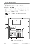
Страница 80: ... the ColorPASS as described in To shut down the ColorPASS on page 4 4 and To open the ColorPASS on page 4 5 2 Disconnect the power supply cable from its connectors on the motherboard and HDD 3 Remove the four screws on the back panel of the ColorPASS that attach the power sup ply to the tray see F04 509 01 on page 4 34 Memo Be sure to hold the power supply while you remove the screws 4 Remove the ...

Страница 81: ... replacement power supply is shipped with screws make sure to use those screws to secure the power supply to the tray 3 Connect the following power supply cable connectors 20 pin power cable to the motherboard power connector PWR CON Large 4 pin power cable to the power connector on the HDD 4 Reassemble the ColorPASS and verify its functionality see Restoring ColorPASS functionality after service ...

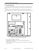
Страница 82: ...inter fonts The HDD is also used to store spooled print jobs Available space on the HDD is dis played on the Control Panel The HDD is installed on the side panel opposite the power sup ply F04 510 01 ColorPASS HDD hard disk drive If you are replacing the HDD you will need The appropriate ColorPASS system software including documentation for the ColorPASS you are servicing Compatible version of the...

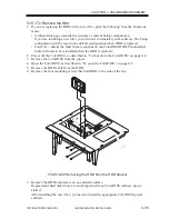
Страница 83: ...hat are resident on the ColorPASS HDD The installed fonts will need to be reinstalled when the HDD is replaced 2 Power off the ColorPASS as described in To shut down the ColorPASS on page 4 4 3 Remove the ColorPASS from the copier 4 Open the ColorPASS as described in To open the ColorPASS on page 4 5 5 Remove the HDD cable from the HDD 6 Remove the four mounting screws that hold HDD to the side of...

Страница 84: ...are sensitive to magnets near the HDD 2 Insert the HDD in the tray and align the mounting holes on the HDD with the four holes on the side of the tray Secure the HDD with the 4 screws Make sure the IDE setting for the HDD is set to master 3 Connect the HDD cable to its connector on the HDD 4 Connect the power supply cable to its connector on the HDD 5 Attach the ColorPASS to the copier 6 Reassembl...

Страница 85: ...b Log Fonts All fonts installed on the ColorPASS HDD are deleted Resident fonts are re stored during system software installation If any additional fonts were downloaded to the ColorPASS the network administrator can reinstall the fonts using Fiery Downloader To determine which additional fonts were downloaded to the ColorPASS print the Font List before you install or restore the system software a...

Страница 86: ...e Configuration page Records the customer s current Setup configuration The Setup configuration will be reset to the default configuration when backup sys tem software is restored Font List the Font List details the fonts that are resident on the ColorPASS HDD Along with the fonts provided the customer may have installed additional fonts that will be deleted when the backup system software is rest...

Страница 87: ...essage Install Fiery press the OK line selection button 7 When a language selection screen appears scroll to the appropriate language and press the OK line selection button 8 Configure Setup using the Configuration page you printed earlier Bypass settings not included on the Configuration page if it is more appropriate for the network administrator to set them See the Configuration Guide for more ...

Страница 88: ... 4 If you have not done so already print the following from the Functions menu if pos sible Configuration page Records the customer s current Setup configuration The Setup configuration will be reset to the default configuration when system software is in stalled Font List the Font List detail the fonts that are resident on the ColorPASS HDD Along with the fonts provided the customer may have inst...

Страница 89: ...age selection screen appears scroll to the appropriate language and press the OK line selection button 12 At the message To complete installation remove CD and recycle power remove the System Software CD and power off and on the system using the power switch on the side panel After the system software is installed the ColorPASS will initialize the system and will also run diagnostics and create a ...

Страница 90: ......

Страница 91: ...COPYRIGHT 2000 CANON INC 2000 2000 2000 ColorPASS Z40e Z20e REV 0 AUG 2000 CHAPTER 5 TROUBLESHOOTING ...

Страница 92: ......

Страница 93: ...suggests areas you should check out before making a call to the customer site With a phone call you can find out if the prob lem is a simple operating failure or a failure caused by a network or configuration change You can ask the customer to check for loose cables on the back of the ColorPASS and loose connections at a power strip or outlet 3 Check for obvious causes of problems Preliminary on s...

Страница 94: ...rally part of a configuration like the one shown below and in F05 102 02 on page 5 3 Problems may occur in one of three areas Inside the ColorPASS In the interface between the ColorPASS and the copier In the interface between the ColorPASS and the workstations or computers to which it is connected F05 102 01 Troubleshooting the system ColorPASS Networked computers or workstations Copier ...

Страница 95: ...OS computers for color copiers or for extensive networks F05 102 02 Functional diagram of a typical configuration Networked computers Network interface Ethernet board SCSI board HDD External Devices SCSI CD ROM drive ColorPASS Motherboard I O Control BIOS CPU PCI Memory Controller IDE interface Memory and interpreter Power supply AC power 3 3 5 12V DC Video board UIB board Operation panel board Co...

Страница 96: ... quality poor Does the ColorPASS fail to appear in the list of printers Has the customer noted any error messages on the ColorPASS or the copier screen If the answer to any of these questions is yes refer the customer to a list of ColorPASS error messages in the Printing Guide 3 Has the customer made any network changes If so request that the customer s network administrator verify the ColorPASS n...

Страница 97: ...stem are plugged into the proper connectors on the back panel of the ColorPASS see F05 104 01 The power cable is plugged into the wall supply The power switch on the side panel of the ColorPASS is powered on F05 104 01 Back panel of ColorPASS If all the connectors are properly in place and the power is on proceed to the next stage of troubleshooting Side panel Power switch Power connector Back pan...

Страница 98: ...cess panel as described in To open the ColorPASS on page 4 5 3 Before you touch any components inside the ColorPASS attach a grounding strap to your wrist and discharge any static electricity on your body by touching the metal cover of the ColorPASS 4 Inspect the inside of the ColorPASS For details see Checking ColorPASS internal connections on page 4 7 Make sure no foreign materials have been dro...

Страница 99: ... 02 Exploded view of ColorPASS components 2 3 4 5 6 8 1 9 14 15 10 11 12 13 7 Key 1 UIB cable 2 Tray 3 HDD cable 4 HDD 5 Power supply 6 Power supply cable 7 Back panel fans and fan cables 8 Motherboard 9 CPU fan CPU fan cable 10 Ethernet board 11 UIB board 12 Video board 13 SCSI board 14 Access panel 15 Top panel ...

Страница 100: ...he red ac tivity light remains on and the error appears on the Control Panel Pressing and holding the fourth line selection button during the startup diagnostics dis plays the Service menu This screen allows you to reinstall system software if required re cover a backup of the system and install options and system software upgrades If the system cannot display the startup diagnostic screen the Col...

Страница 101: ...ber 45005190 Reseat all DIMMs in their sockets and restart the ColorPASS in order to run the startup diagnostics If the error persists replace each DIMM one at a time with a good DIMM until you locate the faulty DIMM s If the above does not correct the error you may need to replace the motherboard Reboot the ColorPASS If the problem persists replace the battery on the motherboard If the problem st...

Страница 102: ... NOTE Reset the time and date in Setup after replacing the bat tery Replace the motherboard Check HDD cable connections to the HDD If that does not correct the problem try replacing the HDD If the problem still persists you may need to replace the motherboard Reboot the ColorPASS If the problem persists replace the battery on the motherboard If the problem still persists you may need to replace th...

Страница 103: ... system error conditions Symptom No fan sound and ColorPASS does not start up No fan sound but the ColorPASS starts up properly Buttons do not work on the Control Panel Probable cause Power supply cable connections are faulty or disconnected Power supply has failed Problem with the back panel fans Connection to the front panel is faulty Connection to the UIB board is faulty or the UIB board has fa...

Страница 104: ...n trying to print Faulty video board System software is cor rupted on the HDD Suggested action Check the UIB cable connections to the top panel and UIB board Check the connection between the motherboard and UIB board If the problem persists replace the UIB board Replace the top panel Restore the system software backup using the Restore Backup function from the Service menu If the problem persists ...

Страница 105: ...st Page is a color file that resides on the ColorPASS hard disk drive a To Print a Test Page from the Control Panel 1 Power on the copier and allow it to warm up 2 Power on the ColorPASS from the power switch on the side panel Messages appear on the Control Panel as the ColorPASS runs through its diagnostics 3 Before proceeding make sure that the copier is not in use The ColorPASS Info screen shou...

Страница 106: ...inal with the output to make sure the connection between the ColorPASS and the copier is working properly a To Run Test Scan Print 1 Place the document that you want to scan on the copier glass 2 At the Idle screen press the menu button once to display the Functions menu F05 301 02 3 Select Run Diagnostics from the Functions menu 4 At the Diagnostics screen select Test Scan Print The message Scann...

Страница 107: ... by the inappropriate Setup options Application specific printing errors caused by missing or incorrectly placed printer de scription files 3 3 Printing to the ColorPASS If the user can print the ColorPASS Test Page but cannot print a job from a computer on the network you may have to make a service call However first make sure the network ad ministrator has Checked all components of the network i...

Страница 108: ......

Страница 109: ...COPYRIGHT 2000 CANON INC 2000 2000 2000 ColorPASS Z40e Z20e REV 0 AUG 2000 CHAPTER 6 PARTS CATALOG ...

Страница 110: ......

Страница 111: ...COPYRIGHT 2000 CANON INC 2000 2000 2000 ColorPASS Z40e Z20e REV 0 AUG 2000 CHAPTER 6 PARTS CATALOG 6 1 FIGURE 100 COLORPASS Z40E PS NX40W PS NX40W A A 15 4 3 2 5 9 7 10 8 13 1 14 12 11 6 16 18 17 19 20 ...

Страница 112: ...13 FE1 5406 000 1 CABLE UIB 14 FE1 5400 000 1 BIOS CHIP 15 FE1 5395 000 1 COVER TOP 16 FE1 5401 000 1 POWER CORD 120V 120V COLORPASS FE1 5402 000 1 POWER CORD 230V 220 240V COLORPASS FE1 5403 000 1 POWER CORD 230V 220 240V PS NX 17 FE1 5404 000 1 POWER CORD 100V 100V 18 FE1 5405 000 1 CABLE INTERFACE COPIER 19 FE1 5381 000 1 CD ROM MEDIAPACK Z40E USA USA COLORPASS FE1 5382 000 1 CD ROM MEDIAPACK Z...

Страница 113: ...ANON INC 2000 2000 2000 ColorPASS Z40e Z20e REV 0 AUG 2000 CHAPTER 6 PARTS CATALOG 6 3 FIGURE KEY NO PART NUMBER DESCRIPTION SERIAL NUMBER REMARKS R A N K Q T Y 100 26 FE1 5390 000 1 CD ROM SYSTEM S W NX40W KANJI PS NX ...

Страница 114: ...COPYRIGHT 2000 CANON INC 2000 2000 2000 ColorPASS Z40e Z20e REV 0 AUG 2000 CHAPTER 6 PARTS CATALOG 6 4 FIGURE 101 COLORPASS Z20E PS NX20W PS NX20W A A 15 4 3 2 5 9 7 10 8 13 1 14 12 11 6 16 18 19 20 ...

Страница 115: ...4 000 1 HDD UNIT 6 0GB 12 FE1 5277 000 1 CABLE HDD 13 FE1 5406 000 1 CABLE UIB 14 FE1 5398 000 1 BIOS CHIP 15 FE1 5395 000 1 COVER TOP 16 FE1 5401 000 1 POWER CORD 120V 120V COLORPASS FE1 5402 000 1 POWER CORD 230V 220 240V COLORPASS FE1 5403 000 1 POWER CORD 230V 220 240V 18 FE1 5405 000 1 CABLE INTERFACE COPIER 19 FE1 5407 000 1 CD ROM MEDIAPACK Z20E USA USA COLORPASS FE1 5408 000 1 CD ROM MEDIA...

Страница 116: ......

Страница 117: ...COPYRIGHT 2000 CANON INC 2000 2000 2000 ColorPASS Z40e Z20e REV 0 AUG 2000 APPENDIX ...

Страница 118: ......

Страница 119: ... Ethernet 10BaseT Supports Adobe PostScript 3 Includes 136 fonts 126 Adobe Type 1 PostScript and 10 TrueType In addition two Adobe Multiple Master fonts are included and are used for font substi tution in PDF files Built in ColorWise color management and NetWise networking management Fiery WebTools ColorWise Pro Tools Fiery Downloader Fiery Link and Fiery Spooler Mac OS only client utilities Fiery...

Страница 120: ...lowing tool in addition to the special tools set T0A 200 01 See Memo Memo A Each service person is expected to carry one B Each group of five service persons is expected to carry one C Each workshop is expected to carry one No Special tool Tool No Shade Rank Remarks 1 Wrist strap CK 0534 000 A 2 IC removing tool CK 0504 000 B ...

Страница 121: ... 0 AUG 2000 PRINTED IN JAPAN IMPRIME AU JAPON Prepared by Office Imaging Products Technical Support Division Office Imaging Products Quality Assurance Center CANON INC Printed in Japan REVISION 0 AUG 2000 35338 5 1 Hakusan 7 chome Toride shi Ibaraki 302 8501 Japan ...

Страница 122: ...PRINTED IN JAPAN IMPRIME AU JAPON 0800AB0 62 1 This publication is printed on 70 reprocessed paper ...

Отзывы: