c) DRAM (IC4)
Controlled by the ASIC, the 4 M-bit DRAM is used as a receive buffer, download
buffer, print buffer, and working area.
d) Paper feed motor driver IC/Carriage motor driver IC (IC15/IC16/IC12)
The paper feed motor driver IC (IC15/16) is a constant-voltage bipolar driver IC.
There are two types of signals that are outputted from the ASIC: a paper feed motor
drive control signal and a head drive control signal. The motor signal output from
the ASIC supplies a constant voltage to each motor phase to control paper feed
motor drive. Also the low voltage output to each terminal controls the head drive.
The carriage motor drive IC (IC12) is a constant-voltage bipolar driver IC. It is
controlled by the motor signals output from the ASIC that supplies a constant
voltage to each phase.
e) EEPROM (IC14)
Controlled by the ASIC, the EDO, TE-CLK and TIDIO signals, the EEPROM data is
read into the ASIC when the hardware/software is powered ON. The data is written
onto the EEPROM when the hardware/software is powered OFF. The data stored in
the EEPROM waste ink absorption amount, fed sheets, BJ cartridge installation and
removal frequencies, function settings, etc.
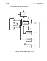
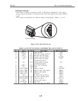
f) Battery Recharge Controller IC (IC2)
In the early stages of recharging, the battery recharge controller first controls the
supply of constant electrical current from the Universal adapter until the set voltage
is reached. This constant current is set to 400 mA. Once the voltage rises to a
predetermined value, the controller switches to maintain a constant voltage. Full
charge is detected by the controller when the recharge current starts to decrease as
it reaches full capacity. Maximum recharging time is set to 6 hours and recharging
is automatically stopped beyond 6 hours as the soft timer keeps track of the total
recharging time.
Part 4: Technical Reference
BJC-50
4-38
Содержание BJC-55 Series
Страница 1: ...BJC 55 SERVICE MANUAL Canon...
Страница 34: ......
Страница 50: ......
Страница 72: ...2 4 Character Code Tables Code page 437 Code page 850 Part 2 Product Specifications BJC 50 2 22...
Страница 73: ...Code page 860 Code page 863 2 23 BJC 50 Part 2 Product Specifications...
Страница 74: ...Code page 865 Code page 857 Part 2 Product Specifications BJC 50 2 24...
Страница 75: ...Code page 855 Code page 852 2 25 BJC 50 Part 2 Product Specifications...
Страница 76: ...Code page 864 Code page 869 Part 2 Product Specifications BJC 50 2 26...
Страница 78: ......
Страница 96: ...3 4 1 Demonstration print Part 3 Operating Instructions BJC 50 3 18 Figure 3 13 Demonstration Print Sample...
Страница 103: ...3 6 4 EEPROM settings list print 3 25 BJC 50 Part 3 Operating Instructions Figure 3 20 EEPROM Settings List Print Sample...
Страница 106: ...Part 3 Operating Instructions BJC 50 3 28 This page intentionally left blank...
Страница 108: ......
Страница 160: ......
Страница 164: ...4 ADJUSTMENT No parts need to be adjusted Part 5 Maintenance BJC 50 5 4...
Страница 198: ...7 CIRCUIT DIAGRAMS 7 1 Parts Layout 7 1 1 Control board Upper section Part 5 Maintenance BJC 50 5 38...
Страница 199: ...7 1 2 Control board Lower section 5 39 BJC 50 Part 5 Maintenance...
Страница 200: ...Part 5 Maintenance BJC 50 5 40 This page intentionally left blank...
Страница 206: ...PRINTED IN JAPAN IMPRIME AU JAPON CANON INC The printing paper contains 70 waste paper...


