


Appendix B - Setting Network ID
MLRemote User's Guide
37
Appendix B - Setting Network ID
Connection Configuration of an MLRemote using a Direct Connection
This mode is used for initial setup and troubleshooting, where the server (typically a field laptop) is directly
connected to the MLRemote
.
For this configuration a direct serial connection to a laptop with MLWebHardware installed is required. The server, or
field laptop, serves as the base.
The following steps the outline process of setting the MLRemote's Network ID on site before installation or in th e
field once the enclosure has been installed.
Setting up a Direct Connection
1. Remove the front plate of the MLRemote by unscrewing the four screws located in the corners of the front of the
enclosure. See section
2.2 Enclosure Installation
.
2. Connect the MLRemote Molex and Battery Molex connectors. See section
2.5 Battery Connection
.
3. Using the custom cable (CAN-MLRemote-CON-CBL), connect the RS-232 Port 2 on the MLRemote module to
the laptop.
4. Make a note of the Serial Number, which is located on the sticker on the side of the MLRemote Module. See
section
2.6 MLRemote Module Serial Number
.
5. Log into MLWebHardware on the laptop and add a new MLBase
.
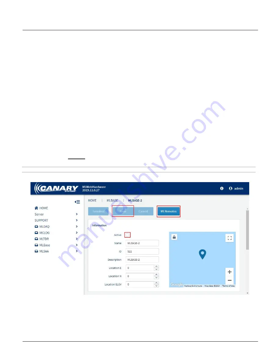
6. Leave the MLBase
inactive
and
Save
the configuration. See “Adding a New Base” in
3.2 MLBase Server
Configuration
of this section for specifics on adding a new MLBase in MLWebHardware.
Hint - Full configuration of the MLBase is not required when setting the Network ID of the MLRemote.
7. Click the
MLRemote
button to add and configure a new MLRemote.


