Canary Systems MLRemote Скачать руководство пользователя страница 28


Section 3 ‒ MLWebHardware Configuration 


28 


      MLRemote User's Guide 
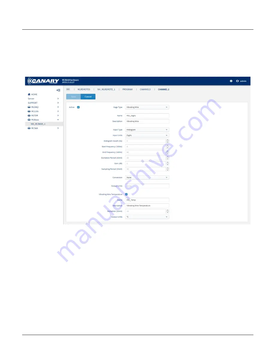
 

Vibrating Wire 

Vibrating wire instruments are configured by selecting "Vibrating Wire" from the 

Gage Type

 drop-down.  

The form displayed includes fields relevant to a Vibrating Wire instrument.    

Update the channel's 

Name

 to reflect something meaningful; this is how the data element is displayed in MLWeb.  

Check the box to include 

Vibrating


Wire


Temperature

 and make any other necessary changes.  

Click 

Save

.   


Click 

Save 

to save the form and return to the Channel list. 

Other Sensor Connections 

Other supported sensor types are configured in the same manor by selecting the designated option from the 

Gage 

Type

 drop-down.  


Содержание MLRemote

Страница 1: ...MLRemote User s Guide Revision A December 2021...

Страница 2: ...Systems warrants products manufactured by Canary Systems excepting software products to be free from defects in materials and workmanship under normal use and service for twelve 12 months from date o...

Страница 3: ...uppliers specifically disclaimany express or implied warranty of fitness for High Risk Activities Documentation and Release Notes To obtain the most recent versionof all Canary Systems technical docum...

Страница 4: ...e page on the Canary Systems websiteto view and download the most current versions of our technical documentation and user s guides at https canarysystems com support users guides The following docume...

Страница 5: ...nection 18 2 6 MLRemote Module Serial Number 18 Section 3 MLWebHardware Configuration 19 3 1 MLBase Configuration 20 Adding a MLBase 20 Information 20 Connection 20 Physical MLBase Connection Configur...

Страница 6: ...graphies using the standard antenna Numerous sensor types are supported including vibrating wire 4 20mA and linear potentiometer Pulse and frequency measurements along with digital status monitoring a...

Страница 7: ...re 40 to 60 C 40 to 140 F Humidity 95 RH Measurement Inputs Vibrating Wire Thermistor Two Digital Counters e g Rain Gage Pulse Flow Meters 2 5VDC to 5VDC Sensors 4 20mA Sensors Analog Measurement Inpu...

Страница 8: ...tection Threshold 90V Transient Current Limit 2kA Models Model Channels Battery Radio Antenna MLRemote Y A 1 Alkaline 900MHz Directional MLRemote O A 1 Alkaline 900MHz Panel Mount MLRemote Y L 1 Lithi...

Страница 9: ...te User s Guide 9 1 3 Inside the Enclosure The figure above highlights theimportant components of the MLRemote The MLRemote and the optional MLMux4 are mounted to a top panel covering the 4 D Cell Alk...

Страница 10: ...ide 1 4 Connections Connections to the MLRemote are provided through multi hole strainrelief fitting at the bottom of the enclosure Cables are fed through the relief fitting and connected to the MLRem...

Страница 11: ...emote are included in table below Contact Canary Systems for more information on these items and optional equipment Quantity Item MLRemote 1 MLRemote Enclosure with standard Antenna Attached Included...

Страница 12: ...ork consisting of a singleMLBase and one or more MLRemotes A Network ID is used to connect the MLBase and MLRemote units on a singlenetwork The devices are shipped programmed with a Network ID of 0 If...

Страница 13: ...tant for best radio communication results The enclosure can be mounted on a pole or the side of a structure Typical pole installationrequires the following materials 3m 10 length of schedule 80 do not...

Страница 14: ...pipe in position overnight See the manufacturer s instructions for the precisecuring time The MLRemote ships with the top plate in place Unscrew the four screws located in the corners of the enclosure...

Страница 15: ...r models that come with a 2 4GHz radio require another type of antenna Contact Canary Systems for antenna options for the 2 4GHz radio Yagi Antenna The 900 MHz 9dBi SS Yagi Antenna bracket mounts to t...

Страница 16: ...els that include an MLMux4 allow up to 4 additional sensors to be connected Hint Models including the MLMux4 are shipped already wired to connect additional Vibrating Wires sensors If using the MLMux4...

Страница 17: ...erial number of the sensor so that the gagefactor is known for each channel The gage factor is taken from the calibration sheet for each sensor The typical colors are as follows Red H1 Coil Black L1 C...

Страница 18: ...d using 16 bit addresses ranging from 001 65535 This address doubles as the module s serial number and is found on the sticker on the side of the MLRemote module inside the enclosure Note This address...

Страница 19: ...ver prior to configuration See the MultiLogger Suite Installation Guide for details on installing MLSuite The steps for configuring the MLBase and MLRemote in MLWebHardware vary depending on the deplo...

Страница 20: ...mation on logging into and navigation in MLWebHardware see the MLWebHardware Users Guide Adding a MLBase Click Add to create a new MLBase in MLWebHardware and to open the MLBase Device Configurationfo...

Страница 21: ...Network ID or RF Level needs to be updated this can be done from the Connection card See Appendix B Updating the MLBase XBee Network ID in the MLBase Users Guide for steps to update the XBee Network I...

Страница 22: ...to a physical MLBase For a virtual configurationit is assumed that the server has a serial connection to a base radio or a device server with serial connection to a radio 1 From the Type dropdown sel...

Страница 23: ...vices Click Add to create a new MLRemote and to open the MLRemote DeviceConfiguration form Information From Device Configuration enter the devices details in the Information card Name the MLRemote som...

Страница 24: ...a physical or virtual MLBase 1 From the Type drop down select MLBase 2 The Network and RF Level are automatically updated to reflect the settings of the MLBase These fields are read only 3 In the Addr...

Страница 25: ...ent Interval and Save This determines how frequently the MLRemote checks in with the MLBase This is when any new programs are sent to the MLRemote and when data is retrieved Click Configure Channels t...

Страница 26: ...ide Channel Configuration Add Channels Click the Add button to add System Information channels and any sensors connected directly to the MLRemote From the Add Channel form sensors and channels are con...

Страница 27: ...rnal Temperature and Internal Humidity Select System Information from the Gage Type drop down By default all system measurements are included To exclude any of the system measurements uncheck the corr...

Страница 28: ...Wire instrument Update the channel s Name to reflect something meaningful this is how the data element is displayed in MLWeb Check the box to include Vibrating Wire Temperature and make any other nec...

Страница 29: ...ed in the MLRemote continue to 3 4 Verify Update and Monitor If an MLMux4 is included in the MLRemote return to the Program Configuration to add and configurethe multiplexer Continue to Multiplexer Co...

Страница 30: ...iplexer Channels Click Configure Channels to open the Multiplexer Channel configurationform and follow the steps outlined previously in Channel Configuration Multiplexer channels are configuring in th...

Страница 31: ...rify Program After all instrumentation and channels have been configured the program should be verified before pushing it to the MLRemote device Click the VerifyProgram button on the Device Configurat...

Страница 32: ...prior to pushing the new program deletes any uncollected data permanently Hint Updating the program does not take effect immediately The program is sent the next time the MLRemote checks in The next c...

Страница 33: ...mote Note This does not display real time data only data collected the last time the MLRemote checked in This is based on the Interval set in section 3 3 Program Configuration For more details on veri...

Страница 34: ...he Server hosting the MLWeb database 3 Select the MLWeb Database name from the dropdown 4 Specify the collection Interval and Offsets this determines the frequency and time which data is imported into...

Страница 35: ...attery voltage and RSSI level are viewed The status of the MLRemote is easily determined by the highlightedcolor the MLRemote Blue New devices that have not yet been configured Green Communication wit...

Страница 36: ...e updated over a serial connection using MLWebHardware 1 From the Firmware update card on the configurationform of the MLRemote the new firmware can be uploaded by clicking theup arrow and choosing a...

Страница 37: ...screwing the four screws located in the corners of the front of the enclosure See section 2 2 Enclosure Installation 2 Connect the MLRemote Molex and Battery Molex connectors See section 2 5 Battery C...

Страница 38: ...meout window Once it has been awake for 20 seconds it will go back to sleep If 20 seconds passes before clicking Test Connection the Reset button must be pressed again 5 Update the Network field to th...

Отзывы: