background image

24


Canarm Tri-Lite 3LMPEC Series

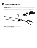
INSTALLING BLADES

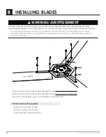
a.

 (Soc Cap 5/16-18 x 5/8) must be installed on the 

inner section of the blade.

b.

 (Soc Cap 5/16-18 x 3/4) must be installed on the 

outer section of the blade.

Each Soc Cap requires one (1) 

c.

 Zinc Split Lock Washer 5/16.

Blade Hardware Kit (supplied):

a.

 (3) Soc Cap 5/16-18 x 5/8

b.

 (3) Soc Cap 5/16-18 x 3/4

c.

 (6) Zinc Split Lock Washer 5/16

1

1

2

2

3

3

4

4

A

A

B

B

C

C

D

D

Page. 30

DRAWN DATE: 

XX.XX.XX

DRAWN BY: 

XX

PART NUMBER: 

XXXX

REV:

_001

THIS DRAWING IS THE EXCLUSIVE PROPERTY OF SKYBLADE FAN COMPANY AND CANNOT BE REPRODUCED OR

DISCLOSED TO ANY THIRD PARTY WITHOUT THE AUTHORIZATION OF SKYBLADE FAN COMPANY

MATERIAL: 

XXXXXXXX

ALL DIMENSION ARE IN INCHES

UNLESS OTHERWISE STATED

b

Top of Blade

c

a

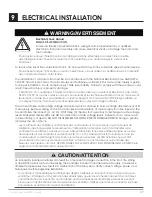
To reduce the risk of personal injury, do not bend the blade brackets when installing the brackets, 

balancing the blades, or cleaning the fan.  Do not insert foreign objects in between rotating fan blades.

Pour réduire le risque de blessure, ne pas plier les crochets lame lors de l’installation les crochets, 

l’équilibre entre les lames, ou de nettoyer la ventilateur. Ne pas insérer d’objets étrangers entre les 

pales du ventilateur.

WARNING/ AVERTISSEMENT

!

Содержание Tri-Lite 3LMPEC

Страница 1: ...Tri Lite 3LMPEC 6 8 HVLS FAN INSTALLATION MANUAL Custom Designed Reduced Maintenance STOL Technology...

Страница 2: ...ordance with all applicable codes and standards including fire rated construction Failure to comply could result in personal injury electric shock death fire and or property damage Before attempting i...

Страница 3: ...ils et ne pas les utiliser des fins autres que celles pr vues par le fabricant This unit has an unguarded impeller Do not use in locations readily accessible to people or animals Cet appareil poss de...

Страница 4: ...WEIGHT 3L06MPEC 6 1 8M Fan 8 203 mm 60 1524 mm 9 229 mm 9 lbs 4 kg 3L08MPEC 8 2 4M Fan 8 203 mm 60 1524 mm 9 229 mm 10 lbs 5 kg 1 Fan Diagram 6 2 Important Information 7 3 Mounting Considerations 8 4...

Страница 5: ...P A R T Y W IT H O U T T H E A U T H O R IZ A T IO N O F S K Y B L A D E F A N C O M P A N Y M A T E R I A L 1 1 S S 3 0 4 A L L D I M E N S I O N A R E I N I N C H E S U N L E S S O T H E R W I S E...

Страница 6: ...ement efficiency by reducing drag MODEL 3L06MPEC 3L08MPEC DIAMETER 6 1 8M 8 2 4M BLADES 3 3 VOLTAGE INPUT 120 230 460 120 230 460 Model Number Ordering Format SERIES DIAMETER BLADES INPUT VOLTAGE PHAS...

Страница 7: ...an closer than 15 of its diameter to any object or its path If this is an issue mounting extension bars and smaller fans are available from Canarm 2 3 Fire Suppression Systems and Fan Placement If ins...

Страница 8: ...e event of this max torque being applied is unlikely and will only apply due to a failure of the variable frequency drive and its soft start technology 3 4 Safety Cable A Canarm fan should never be ru...

Страница 9: ...t The spacing between multiple fans should be no less than 2 5x the fans diameter when measured from the center of the fans The mounting structure must be able to withstand the torque which is generat...

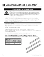
Страница 10: ...pport Directly From Building Structure All mounting instructions assume that the building structure from which the fan will be hung is of sound construction undamaged and capable of supporting loads o...

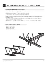
Страница 11: ...cture du toit chaque extr mit Fasten the unistrut to the roof structure mounting points at each end with customer supplied Grade 5 hardware as shown Fixez l unistrut aux points de fixation de la struc...

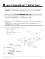
Страница 12: ...nt destin es aux installations de faisceaux WARNING AVERTISSEMENT Do not install the fan from a single purlin truss or bar joist Ne pas installer le ventilateur partir d une seule panne botte ou soliv...

Страница 13: ...Irons Together if span is longer than 8 If the angle iron span is 8 2 4m or less proceed to step 5 6a on the following page If the angle iron span is longer than 8 2 4m it is necessary to use double...

Страница 14: ...e Washer see diagram d 4 1 2 Nylock Nut 2 5 6 4 cm 9 16 Dia 1 4 cm 2 5 6 4 cm Do not install the fan from a single purlin truss or bar joist Ne pas installer le ventilateur partir d une m me purlin bo...

Страница 15: ...Nylock Nut Do not install the fan from a single purlin truss or bar joist Ne pas installer le ventilateur partir d une m me purlin botte ou solives The angle irons must be fastened to the roof struct...

Страница 16: ...EXCLUSIVE PROPERTY OF SKYBLADE FAN COMPANY AND CANNOT BE REPRODUCED OR DISCLOSED TO ANY THIRD PARTY WITHOUT THE AUTHORIZATION OF SKYBLADE FAN COMPANY MATERIAL XXXXXXXX ALL DIMENSION ARE IN INCHES UNL...

Страница 17: ...roceed to Hanging the Fan on pg 21 Clamping Plate Hardware supplied a 4 1 2 13x2 1 2 GR 5 Bolt b 8 1 2 Flat Washer c 4 1 2 13 Nylock Nut d 2 Clamping Plate a b c b d I Beam Flange Width Upper Yoke Mou...

Страница 18: ...aced on both sides of the plate for each bolt 5 12 Pre Drill Angle Iron Brackets Holes Your angle iron should be cut to allow 1 2 1 27 cm clearance between the end of the angle iron and the purlin you...

Страница 19: ...the purlin brackets 5 15 Attach Upper Yoke to Angle Iron Attach the upper yolk to the angle irons using the provided 1 2 grade 5 bolts washers and nylock nuts See section 5 7 Attach Upper Yoke to Ang...

Страница 20: ...1 2 Flat Washer c 2 1 2 16 Nylock Nut 6 2 Secure Upper Safety Cable Secure the safety cable to the I beam or angle iron by wrapping the safety cable around it threading the cable through the 17 32 ope...

Страница 21: ...vitesses ce qui peut entra ner des dommages ou une dur e de vie raccourcie Ne pas installer le niveau annulera la garantie du fabricant WARNING AVERTISSEMENT 6 3 Attach the Motor to extension tube At...

Страница 22: ...erence Eye Hook illustration on page 23 1 Slide the unlooped end of the guy wire through the eye hook 2 Feed the wire through the loop on the other end of the wire 3 Pull tight so the wire tightens on...

Страница 23: ...ing a Beam Clamp b Eye Hook c Gripple Wire Loop Gripple Maximum Angle Gripple Hook Tab Motor Make certain all electrical cords are not obstructed by guy wires Assurez vous que tous les c bles lectriqu...

Страница 24: ...THE EXCLUSIVE PROPERTY OF SKYBLADE FAN COMPANY AND CANNOT BE REPRODUCED OR DISCLOSED TO ANY THIRD PARTY WITHOUT THE AUTHORIZATION OF SKYBLADE FAN COMPANY MATERIAL XXXXXXXX ALL DIMENSION ARE IN INCHES...

Страница 25: ...IS THE EXCLUSIVE PROPERTY OF SKYBLADE FAN COMPANY AND CANNOT BE REPRODUCED OR DISCLOSED TO ANY THIRD PARTY WITHOUT THE AUTHORIZATION OF SKYBLADE FAN COMPANY MATERIAL XXXXXXXX ALL DIMENSION ARE IN INC...

Страница 26: ...be positioned on top of the boomerang bracket of the blade previous First install all boomerang brackets and hardware by hand tightening Second tighten the blade bolts individually with a 1 4 allen wr...

Страница 27: ...are Kit supplied a 3 BTN Cap Screw 10 32 X 3 8 Wingtip Wingtip Blade 2 2 3 3 4 4 A B C D Page DRAWN DAT XX XX XX DRAWN BY XX THIS DRAWING IS THE EXCLUSIVE PROPERTY OF SK DISCLOSED TO ANY THIRD PARTY W...

Страница 28: ...c voltages supply voltage variations voltage dips and frequency time deviation Canarm n est pas responsable des perturbations de tension en r f rence explicite aux interf rences magn tiques lectroniqu...

Страница 29: ...rom line inputs at the fan controllers disconnect L1 L2 L3 Wait three 3 minutes for capacitors to discharge to safe voltage levels Darkened display LEDs are NOT an indication of safe voltage levels Fa...

Страница 30: ...stallation CAUTION ATTENTION IMPORTANT Check that the correct input voltage is being sent to the fan See rating labels on the motor for acceptable voltage A blown fan due to incorrect input voltage is...

Страница 31: ...Input Power Cable Wiring Schematics IMPORTANT Grounding of the incoming power on the motor is required NOTE Canarm suggests using a field supplied fused disconnect switch 1 Phase Voltage 120V 3Ph 230V...

Страница 32: ...o a Fire Alarm Panel If the installation of the fan is required to be wired to a fire alarm emergency shut off an external relay will have to be placed by a fire suppression specialist between the vol...

Страница 33: ...ding at the motor controller and from the controller to the supply b Do not run your controller and sensitive equipment on the same power line c Install properly sized EM RFI filter d Contact Customer...

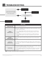
Страница 34: ...h Canarm fans Is the input voltage correct Fix incorrect wiring Is the fan making any noise End of troubleshooting Yes Yes Yes No No No Check splices and wiring at the controller Is the Wiring correct...

Страница 35: ...lt may be occurring a line reactor may need to be placed to reach correct voltage If the voltage is low at splice of the fan motor Under volt may be occurring a line reactor may need to be placed to r...

Страница 36: ...Aluminum PP 138 Motor H30 3 Ph PP 015 5 Extension Bar 5 ft Aluminum PP 172 6 6 Mini Blades PP 027 Chassis Silver PP 172 8 8 Mini Blades PP 029 Chassis Bottom Plate Steel PP 182 Red Wing Tip BP 031 Pur...

Страница 37: ...ury to persons during cleaning and user maintenance Risque d incendie de choc lectrique ou de blessures lors du nettoyage et de l entretien par l utilisateur Disconnect the appliance from the power su...

Страница 38: ...38 Canarm Tri Lite 3LMPEC Series 12 USER SERVICING INSTRUCTIONS Maintenance Log Replacement Part List DATE MAINTENANCE PERFORMED REPLACEMENT PARTS REQUIRED PART NO DESCRIPTION...

Страница 39: ...Canarm Tri Lite 3LMPEC Series 39 NOTES...

Страница 40: ...LIM3LMPEC 0123_03 PHONE 1 613 342 5424 FAX 1 800 263 4598 E Mail hvacsales canarm ca www canarm com...

Отзывы: