


CJF - AC/EC SERIES CANARM JET FAN
CJF_AC_EC_Series_JULY 2021
Page 5 of 6
www.CANARM.COM
Canarm Ltd. - Corporate Head Office
2157 Parkedale Avenue, PO Box 367 Brockville, Ontario Canada K6V 5V6
Tel: (613) 342-5424 Fax: (613) 342-8437
www
.canarm.com
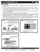
All maintenance and wiring should be completed by a qualified electrician in accordance with National & Local
1.
Electrical Codes.
Ensure power supply is disconnected and that the unit is locked out prior to performing any work on the CJF.
2.
The unit will have all power wires routed to an externally mounted wiring box. Refer to the wiring diagram
3.
provided inside the electrical box cover or in this manual for further instruction.
It is recommended that all maintenance is done on the ground and NOT on the ceiling. There is a significant risk
4.
of falling weight.
See Figure 8
With the unit safely on the ground remove the guard screen as per
Figure 5
5.
The CJFs are designed for easy maintenance. Once you remove remove the 12x bolts securing the service panel,
6.
and the electrical box, secure the motor core and then the whole assembly may be lifted out for service.
See
Figures 9 & 10.
Make sure to use proper lifting methods as some motor cores are very heavy.
When maintenance is complete, replace the core into its housing, reversing the steps shown in
Figures 10 & 9,
7.
replace the guard screen
(Figure 5)
and prepare to lift and re-attach the unit to the ceiling.
MAINTENANCE
!"#
URE
%?'
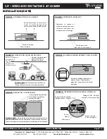
SAFELY LIFTING
&2*1(&)*"&+#'($%(#(!%&
+,-.'
PJ:&>B=E&6II7>G:8&=AC@AB<&
F:@N>8J&6B8&J6C:@E&?6D@A>BJQ
":F>G:&F>DB@AB<&N678967:&
6B8&=>9:7&DBA@&C>7&F6AB@:B6B?:
!"#
URE
%@'
+*$*"&!*"%&"%+*R#-&)*"&/%"R'!%
":F>G:&6==&Y
2
;>=@J&=>?LAB<&
F>@>7&?>7:&@>&@N:&N>DJAB<&
":F>G:&:=:?@7A?6=&;>O&C7>F&@N:&DBA@&
N>DJAB<&9A@N&6&bUYc&87AG:7K&d::I&=AeDA8&@A<N@&
?>B8DA@&6@@6?N:8K
!"#$%
10
'
+*$*"&!*"%&"%+*R#-
+,-.'
PJ:&>B=E&6II7>G:8&=AC@AB<&
F:@N>8J&6B8&J6C:@E&?6D@A>BJQ
!67:CD==E&ID==&8A7:?@=E&DI9678J&>B&
F>@>7&F>DB@AB<&67FJ&@>&7:F>G:&
F>@>7&?>7:K


