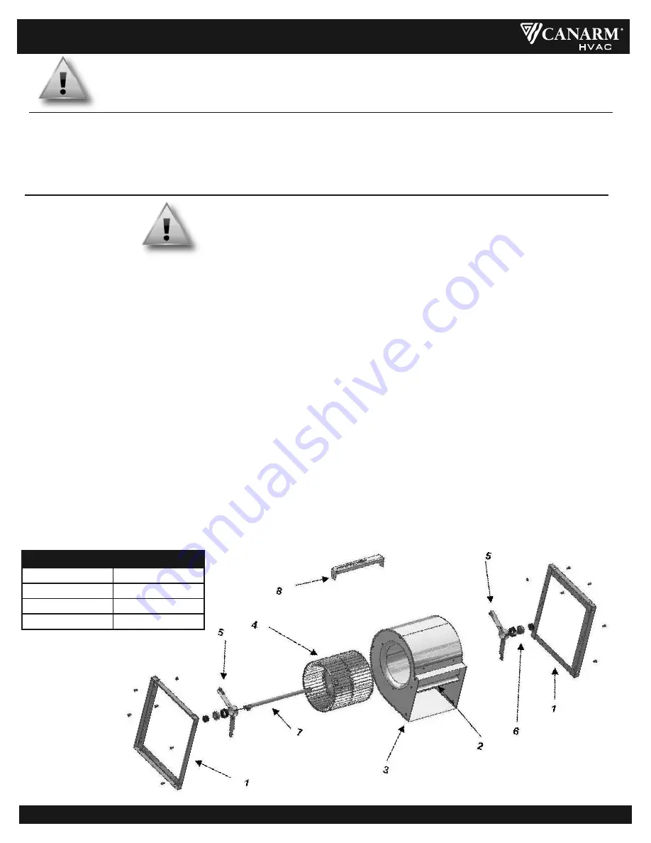
FIGURE 8: EXPLODED VIEW (800 SERIES)
Refer to
Figure 3
(900 Series) for an illustration on T-Bar’s and Pillow block bearings.
1.
Framework
5.
Bearing Bracket
2.
Baffle
6.
Ball Bearing Assy
3.
Housing
7.
Shaft
4.
Wheel
8.
Motor Bracket
PARTS LIST
WARNING
ENSURE PO
w
ER SUPPL
y
IS DISCONNECTED & LOCkED OUT PRIOR TO MAkIN
g
ELECTRICAL CONNECTIONS.
1.
Inspect and tighten all bearing collar and wheel set screws after the first 50 to 100 hours of operation and periodically thereafter.
2.
Follow motor manufacturer's instructions for motor lubrication. Remove any excess lubrication.
3.
Check the drives.
a.
Tighten set screws on pulleys, wheel and bearing locking collars.
b.
Check belt tension and alignment.
c.
Replace cracked or worn belts.
4.
Blower bearings are permanently lubricated and require no further lubrication.
5.
Inspect V-belts for wear and proper tension. If it is necessary to replace one belt on a multiple belt drive, replace all the belts with a
matched set. Do not use belt dressing.
6.
Clean the blower wheel periodically. Material build up on the blades can cause wheel imbalance which may result in wheel or bearing failure.
7.
To reinstall replacement ball bearings on spider bearing bracket assemblies, press the locking collar against the inner ring of the bearing and
turn in the direction of the shaft rotation until engaged. Insert a drift pin into the pin hole and tap lightly to set. Tighten set screw on locking
collar firmly. (see
Figure 7)
.
If replacing the pillow block bearings, simply loosen the set screws and remove the mounting hardware. When
re-installing, bolt the pillow block to the T-bar support, then position the set screw to be parallel and on top of the key stock of the shaft.
Torque set screw to specified values.
8.
Spider bracket bearings come pre-lubricated from the manufacturer, and require no re-lubrication. Pillow block bearings are pre-lubricated
by the manufacturer. Generally, these bearings should be lubricated at six to twelve month intervals. The recommended lubricant is Shell
Alvania #2 or S3. A small amount of grease should be added slowly when the shaft is rotating.
Note: Over greasing may cause dam
age to the bearing. Avoid rupturing the bearing seal.
9.
Should further service to the blower be necessary, refer to the exploded view illustration (see
Figure 8).
MAINTENANCE
1.
Complete the electrical connections, energize the unit momentarily and ensure proper wheel rotation.
2.
Apply full power.
3.
With all ducts attached, the access doors in place and the air system in full operation, measure the motor current and ensure that it is
less than the rated full load motor amperage as indicated on the motor nameplate.
OPERATION
400/800/900 SERIES UTILITY BLOWERS
400_800_900 SERIES_04_08_2022
Page 4 of 4
WARNING
A
g
ROUND
w
IRE MUST
b
E CONNECTED FROM THE UNIT CHASSIS TO A SUITA
b
LE ELECTRICAL
g
ROUND.


