background image

Canarm Tri-Lite 3LEC Series 

29

10 

Electrical Installation

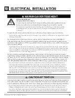
WARNING/AVERTISSEMENT

!

!

An incorrectly installed controller can result in component damage or reduction in the fan’s life. Wiring or application 

errors such as under-sizing the controller, incorrect or inadequate AC supply, or excessive ambient temperatures may 

result in a malfunction of the fan system. Verify correct voltage, phase, and horsepower before beginning installation.

Un contrôleur mal installé peut entraîner des dégâts matériels ou la réduction de la durée de vie du ventilateur. 

Câblage ou d’application des erreurs telles que le sous-dimensionnement du contrôleur, une alimentation ca 

incorrecte ou inadaptée ou des températures ambiantes excessives peuvent provoquer un dysfonctionnement du 

système de ventilation. Vérifiez que la tension correcte, la phase et puissance avant de commencer l’installation.

CAUTION/ATTENTION

!

Electrical Shock Hazard.

RISQUE D’ÉLECTROCUTION.

To reduce the risk of electrical shock, wiring should be performed by a qualified electrician. 

Incorrect assembly can cause electrical shock or damage the motor and the controller.  

Pour réduire le risque d’électrocution, le câblage doit être effectué par un électricien qualifié. 

Assemblage incorrect peut provoquer des chocs électrique ou endommager le moteur et le 

contrôleur.

To reduce the risk of fire or electrical shock, do not use this fan with any solid-state speed control device.

Pour réduire le risque d’incendie ou de choc électrique, ne pas utiliser ce ventilateur avec un dispositif de contrôle 

de vitesse à l’état solide.

The installation of a Tri-Lite Fan must be in accordance with the National Electrical Code, ANSI/NFPA 70-

1999, and all local codes. The procedures and techniques outlined in this manual are merely a guide for proper 

installation. Code compliance is YOUR responsibility. Failure to comply with these codes could result in personal 

injury or property damage.

L’installation d’un ventilateur Tri-Lite doit être en conformité avec le National Electrical Code, ANSI / NFPA 70-

1999, et tous les codes locaux. Les procédures et les techniques décrites dans ce manuel sont seulement un guide 

pour une installation correcte. Respect du Code est de VOTRE responsabilité. Le non respect de ces codes peut 

entraîner des blessures ou des dommages matériels.

The fan controllers contain high voltage capacitors which continue to hold a charge after removal of its main 

supply. Before working on the fan controller, ensure isolation of mains supply from line inputs at the fan controllers 

disconnect (L1, L2, L3). Wait three (3) minutes for capacitors to discharge to safe voltage levels. Darkened display 

LEDs are NOT an indication of safe voltage levels. Failure to do so many result in personal injury or death. DO 

NOT DISASSEMBLE THE MOTOR OR ITS ONBOARD DRIVE! Doing so greatly increases the risk of shock.

Les contrôleurs de ventilateur contiennent des condensateurs à haute tension qui continuent de maintenir 

une charge après l’enlèvement de l’alimentation principale. Avant de travailler sur le contrôleur du ventilateur, 

assurez-vous que l’alimentation électrique des entrées de ligne au niveau des disjoncteurs des ventilateurs se 

déconnecte (L1, L2, L3). Attendez trois (3) minutes pour que les condensateurs se déchargent à des niveaux de 

tension sécurisés. Les LED éclaircies ne sont PAS une indication de niveaux de tension sécurisés. Le fait de ne 

pas faire beaucoup entraîne des blessures corporelles ou la mort. NE DÉMONDEZ PAS LE MOTEUR OU SON 

ENTRAÎNEMENT À BORD! Cela augmente considérablement le risque de choc.

Содержание 3LEC Series

Страница 1: ...Tri Lite Fans 3LEC Series 6 24 Installation Manual Custom Designed Reduced Maintenance Direct Drive STOL Technology Patent pending...

Страница 2: ...all applicable codes and standards including fire rated construction Failure to comply could result in personal injury electric shock death fire and or property damage Before attempting installation s...

Страница 3: ...ls et ne pas les utiliser des fins autres que celles pr vues par le fabricant This unit has an unguarded impeller Do not use in locations readily accessible to people or animals Cet appareil poss de u...

Страница 4: ...P 14 32 0 94 0 19 0 70 lbs 3L16EC V P 16 32 0 94 0 19 0 80 lbs 3L18EC V P 18 32 0 142 0 19 0 100 lbs 3L20EC V P 20 32 0 142 0 19 0 110 lbs 3L24EC V P 24 32 0 142 0 19 0 120 lbs 1 Fan Diagram 6 2 Impor...

Страница 5: ...the installer Notify your product representative or Canarm of any discrepancy or missing kit contents prior to installing unit Wingtip Fence x3 Airfoil x3 Control Box x1 Strain Relief Bushing x1 Motor...

Страница 6: ...embly E Chassis Housing for the motor and gear reducer F Airfoil Provides air movement G Wingtip Fence Improves air movement efficiency by reducing drag H 4 Point Safety Cables Used as a redundant saf...

Страница 7: ...ing the fan closer than 15 of its diameter to any object or its path If this is an issue mounting extension bars and smaller fans are available from Canarm 2 3 Fire Suppression Systems and Fan Placeme...

Страница 8: ...seconds The event of this max torque being applied is unlikely and will only apply due to a failure of the variable frequency drive and its soft start technology 3 4 Safety Cable A Tri Lite fan should...

Страница 9: ...equipment The spacing between multiple fans should be no less than 2 5x the fans diameter when measured from the center of the fans The mounting structure must be able to withstand the torque which i...

Страница 10: ...de serrage que si l paisseur de la semelle de la poutre sup rieure 3 8 1 cm Les trous de fixation de la cale sont plus pr s d un c t que de l autre Assurez vous que ce c t est confront la poutre CAUTI...

Страница 11: ...from a single purlin truss or bar joist Ne pas installer le ventilateur partir d une seule panne botte ou solives Unsupported angle iron spans should not exceed 12 3 7m Non pris en charge trav es de...

Страница 12: ...Irons Together if span is longer than 8 If the angle iron span is 8 2 4m or less proceed to step 6 4a on the following page If the angle iron span is longer than 8 2 4m it is necessary to use double a...

Страница 13: ...Washer see diagram d 4 1 2 Nylock Nut Do not install the fan from a single purlin truss or bar joist Ne pas installer le ventilateur partir d une m me purlin botte ou solives The angle irons must be...

Страница 14: ...ylock Nut Do not install the fan from a single purlin truss or bar joist Ne pas installer le ventilateur partir d une m me purlin botte ou solives The angle irons must be fastened to the roof structur...

Страница 15: ...2 13 Nylock Nut The angle irons should be aligned with the innermost holes of the upper yoke Les fers angulaires doivent tre align s avec les trous les plus l int rieur de la culasse sup rieure After...

Страница 16: ...ed on both sides of the plate for each bolt 6 9 Pre Drill Angle Iron Brackets Holes Your angle iron should be cut to allow 1 2 1 27 cm clearance between the end of the angle iron and the purlin you ar...

Страница 17: ...d to the outside faces of the purlin brackets 6 12 Attach Upper Yoke to Angle Iron Attach the upper yolk to the angle irons using the provided 1 2 grade 5 bolts washers and nylock nuts See section 6 5...

Страница 18: ...ult in damages to the fan and building or even personal harm Canarm is NOT liable for any damages or injury resulting from improper installation Calculs de masse doit tre fait pour s lectionner le uni...

Страница 19: ...hannels with open sides facing away from each other onto threaded rods using 1 2 washers and 1 2 13 nylock nuts thus sandwiching the top chord of the joist Torque to 90 ft lbs 6 Route safety cable thr...

Страница 20: ...ivot Hardware supplied a 2 1 2 13 x 3 1 2 GR 5 Bolt b 4 1 2 Flat Washer c 2 1 2 13 Nylock Nut 7 2 Secure Upper Safety Cable Secure the safety cable to the I beam or angle iron by wrapping the safety c...

Страница 21: ...4 1 2 Flat Washer c 2 1 2 13 Nylock Nut 7 4 Attach Motor Chassis to lower yoke Attach the motor frame to the lower yoke with the Motor Hub Hardware as shown Tighten bolts to 90 ft lbs 122 N m using a...

Страница 22: ...e Eye Hook illustration on page 23 1 Slide the unlooped end of the guy wire through the eye hook 2 Feed the wire through the loop on the other end of the wire 3 Pull tight so the wire tightens on the...

Страница 23: ...Ceiling a Beam Clamp b Eye Hook c Gripple Wire Loop Gripple Maximum Angle Gripple Hook Tab Motor Ceiling Beam 45 Maximum Guy Wire a b c Make certain all electrical cords are not obstructed by guy wire...

Страница 24: ...des Pour r duire le risque de blessure ne pas plier les crochets lame lors de l installation les crochets l quilibre entre les lames ou de nettoyer la ventilateur Ne pas ins rer d objets trangers entr...

Страница 25: ...Canarm Tri Lite 3LEC Series 25 9 installing Airfoils 9 1a Attach Airfoils to Hub Slide airfoil onto struts until airfoil holes and strut holes are aligned...

Страница 26: ...6 18 Nylock Nut ATTENTION Upon completion of the mechanical installation of the fan and before powering on spin the fan around multiple times by hand to ensure all brackets are clear from contact with...

Страница 27: ...ly Install wingtips on end of airfoil after airfoil has been securely attached to the strut Using a Phillips head screwdriver fasten wingtip to airfoil using a 6 x 5 8 Flat Phil Screw Wingtip Hardware...

Страница 28: ...ance pr matur e et annulera la garantie du fabricant 10 Electrical Installation 10 1 Power Requirements Input Voltage Input Hz Input Output Phase 198 264 230V 50 60 Hz 3 3 Phase 320 480 460V 50 60 Hz...

Страница 29: ...and all local codes The procedures and techniques outlined in this manual are merely a guide for proper installation Code compliance is YOUR responsibility Failure to comply with these codes could re...

Страница 30: ...endommag ou dangereux Ne pas tenter de r soudre les dysfonctionnements lectriques ou des checs sur votre propre Contactez Canarm au 1 613 342 5424 si vous avez des questions concernant l installation...

Страница 31: ...agram INPUT LINE VOLTAGE REMOTE SWITCHBOX SPEED POT VIEWED FROM BACK FOR REV SWITCH VIEWED FROM BACK Green GND 1 White Reverse Brown Analog In 0 10v Red Speed 10 Volts Green GND 1 White Reverse Brown...

Страница 32: ...re slot on the top of the chassis allows the power wire to be ran through or affixed to the side of the extension bar then conveniently through the top plate of the chassis and directly in to the moto...

Страница 33: ...ing at the motor controller and from the controller to the supply b Do not run your controller and sensitive equipment on the same power line c Install properly sized EM RFI filter d Contact Customer...

Страница 34: ...and lock the service disconnecting means to prevent power from being switched on accidentally Avant de r parer ou de nettoyer l appareil coupez l alimentation lectrique au panneau de service et bloque...

Страница 35: ...controller and ensure their tightness 5 Ensure airfoils are secured to one another by boomerang brackets 6 Ensure screws securing wingtip fences to airfoils are tight 7 Check for the presence of the...

Страница 36: ...www canarm com CANARM LTD PHONE 1 800 267 4427 FAX 1 800 263 4598 E Mail hvacsales canarm ca...

Отзывы: