background image

8

of 42

Combustex BMS-2000 [5.03] Operations Manual - 

2. OPERATION

Phone:

 403.342.4494        

|


Web:

 www.canaltaflow.com

For operational, technical or installation assistance, please contact us.

Call Us Toll Free: 

1-855-226-2582

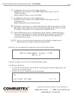
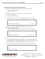
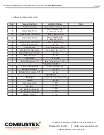
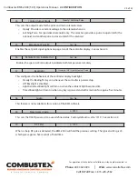
Upon power-up, the introduction message and controller version will be displayed:

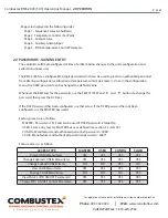
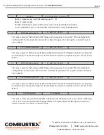
From the main display, the user can scroll through five different pages.

To enable the scroll function:

1.  Press the ‘PAGE SCROLL’ button.  Notice that the 

>

 symbol appears beside the page number in the 

top left-hand corner of the display.

2.  Press the 


and


buttons to go to the desired page.

Burner Management System V 5.03

REV 2.xx

1>

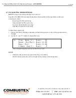
Low Input Voltage 


     1 of 3

•   

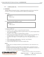
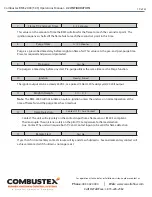
CONFIG allows the user access to the Configuration Menu.


Note:

 BMS must be shut down (

not in NORMAL OPERATION

) in order to access the  


Configuration Menu.  


Note:

 Configuration Menu is password protected.

•   

CALIB allows the user access to the Calibration Menu.

 Note:

 BMS must be shut down (

not in NORMAL OPERATION

) in order to access the  


Calibration Menu.  


Note:

 Calibration Menu is password protected.

•   

PAGE SCROLL / EXIT displays a 

>

 symbol beside the page number in the top left corner of the         

       BMS display, indicating that the user may scroll through the pages by pressing the arrow keys.      

       PAGE SCROLL is also used to exit the Configuration and Calibration Menus.

•   

SELECT ITEM allows the user to scroll through any active shutdowns on BMS display page 1,    


change the control parameters on page 2, and adjust settings on pages 4 and 5 (using the  


arrow keys).  SELECT ITEM also moves the cursor from right to left when inputting any    


password or numerical value.

•   

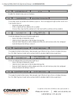
         The arrows are used to scroll through pages, scroll through the Configuration and   


        Calibration Menus, and adjust settings and numerical values.

Содержание Combustex BMS-2000

Страница 1: ...Combustex BMS 2000 O P E R AT I O N S M A N U A L O P E R AT I O N C O N F I G U R AT I O N C A L I B R AT I O N I N S TA L L AT I O N B149 3 Compliant Burner Mangagement System BMS Software Version 5...

Страница 2: ...ain system security through password protection Access a wide selection of sequencing monitoring and control information through easy page scrolling on the heated back lit display Gain flexibility wit...

Страница 3: ...G THIS EQUIPMENT IS SUITABLE FOR USE IN CLASS 1 DIVISION 2 GROUPS B C D OR NON HAZARDOUS LOCATIONS ONLY WARNING EXPLOSION HAZARD DO NOT DISCONECT EQUIPMENT WHILE CIRCUIT IS LIVE UNLESS AREA IS KNOWN T...

Страница 4: ...nce Status Shutdown Annunciation 2 4 Temperature Control 2 5 Output Status 2 6 Auxiliary Analog Inputs and Shutdowns 2 7 PID Control Parameters 3 CONFIGURATION OF THE BMS 2000 3 1 Overview 3 2 Configu...

Страница 5: ...ath Another fluid oil or gas is routed through the bath to be heated This is referred to as the Process The BMS will control up to two pilots and two main burners handle temperature control of the bat...

Страница 6: ...tact Low Bath Level Burner 1 Main Valve Proof of Closure 3 Additional inputs for Dual Burner Systems Burner 2 Flame Sensor Failure Burner 2 Flame Failure to Relight Burner 2 Fuel Gas Low Pressure Burn...

Страница 7: ...lsed Wide variety of configurable safety interlock devices factory set to standard settings Remote start stop is configurable Auto startup after power failure is configurable Intermittent pilot or sta...

Страница 8: ...ed to above to calculate total Total current draw not to exceed 3A Display Low Temp Heated LCD Mounting Wall Mount Bracket Standard 2 Pipe Mount Optional Communication Digital Analog and Modbus 1 7 DE...

Страница 9: ...Note the BMS display must read CLEAR TO START in order to initiate startup sequence STOP cancels the ignition sequence and or shutdown the operation of the BMS and pilot by closing all fuel train valv...

Страница 10: ...r to access the Configuration Menu Note Configuration Menu is password protected CALIB allows the user access to the Calibration Menu Note BMS must be shut down not in NORMAL OPERATION in order to acc...

Страница 11: ...been configured use that value If the USER password has not been configured use the MASTER password Factory presets are as follows MASTER Password is 1313 and can be used if USER password is forgotten...

Страница 12: ...buttons In the example below three shutdowns are active the first of which is due to low voltage All shutdowns must be cleared before being permitted to proceed To clear them 1 Satisfy the shutdown c...

Страница 13: ...e appears after depressing the START button ignitor is on Preset Trial for Ignition Period The following message is displayed once the system has verified the pilot flame If after reaching Normal Mode...

Страница 14: ...le viewing this page the operator can Adjust the Local Set Point Switch between Local Remote or Serial Set Point Control Adjust Manual Control s Output Value To make these changes 1 Depress the SELECT...

Страница 15: ...X ANALOG INPUTS AND SHUTDOWNS Page four of the BMS 2000 controller displays two monitored values Spare Thermocouple Input 1 if selected This value can be labeled as 1 Stack Bath or Process Input can b...

Страница 16: ...roportional for PID control only Integral Reset for PID control only Derivative Rate for PID control only Dead Band for ON OFF control only To make these adjustments 1 Depress the SELECT ITEM key repe...

Страница 17: ...t of options 4 When a numerical value appears and the cursor is flashing the value is open for adjustment Use the SELECT ITEM key to move the cursor and the and buttons to change it 5 If a numerical v...

Страница 18: ...F Preset at 250 C 482 F N A when Flame Detection config ured to Contact flame rod UV 5 2 T C Flame 2nd Level 0 800 C 32 1472 F Preset at 450 C 842 F N A when Flame Detection config ured to Contact fla...

Страница 19: ...te Only 0 800 C 32 1472 F 26 Spare Temp 2 T C Label Stack 2 Bath Process 27 Allow Auto Manual Yes No 28 Control Mode None Proportional On Off 29 Main Bath T C High Temp No 0 600 C 32 1112 F 30 Bath Hi...

Страница 20: ...into Normal Operation upon crossing this set point Preset at 450 C 842 F This value represents the first level of the flame proving sequence for burner 2 if Flame Detection is configured to Thermocou...

Страница 21: ...utput can be a steady 24VDC or a pulsed 5 Hertz 20 duty cycle 24 Volt output Note The BMS 2000 will not initiate an auto re ignition unless the unit was in normal operation at the time of flame fail a...

Страница 22: ...ll require proof of closure from burner 2 main valve before ignition sequence will be enabled When utilizing ON OFF temperature control the main burner is cycled on and off to maintain bath and or pro...

Страница 23: ...umeric temperature setting is crossed This applies the label to the previous thermocouple input Whatever tag is chosen is displayed on page five The Bath tag here should not be confused with the dedic...

Страница 24: ...the bath T C for HTSD Yes Controller will use the bath T C for HTSD and will shut down when this configured numeric temperature setting is crossed Recommended as a fall back to the bath high temperatu...

Страница 25: ...nfigures the behaviour of the controller display backlight Steady On Backlight stays on whenever the controller is powered up Off Backlight is disabled Light Activated Backlight will turn on when the...

Страница 26: ...Free 1 855 226 2582 This sets the filter which mathematically smooths noisy signals for the pilot and spare thermocouple input This sets the filter which mathematically smooths noisy signals for the b...

Страница 27: ...Scroll to the Zero value of the input to be calibrated 3 Press the ACK key A flashing cursor allows the value to be changed 4 Use the SELECT ITEM key to move the cursor 5 Use the and buttons to chang...

Страница 28: ...2 1472 F Type K Thermocouple Input Spare 2 Temp Zero Value 0 800 C 32 1472 F Type K Thermocouple Input Spare 2 Temp Span Value 0 800 C 32 1472 F Type K Thermocouple Input Remote Set Point Zero 4ma 0 8...

Страница 29: ...0 25 751 180 7 338 640 26 599 200 8 137 660 27 445 220 8 938 680 28 128 240 9 745 700 28 288 260 10 560 720 29 165 280 11 381 740 30 799 300 12 207 760 31 629 320 13 039 780 32 455 340 13 874 800 33 2...

Страница 30: ...r tight seal through the use of a Myers Hub or other approved CEC wiring methods Wiring Methods 1 Use rigid steel or aluminum conduit 2 Interconnecting wiring Power to the BMS and interconnecting powe...

Страница 31: ...re available 1 Remote Stop 2 Remote Start 3 Flame Detection 1 Input 4 Flame Detection 2 Input 5 Low Bath Level 6 Aux High Temp 7 Low Fuel Pressure Burner 1 8 Low Fuel Pressure Burner 2 9 Proof of Clos...

Страница 32: ...3 SD indication ON when there are no shutdowns active OFF when there are any shutdowns active 15 Pilot 1 Unlatch available upon request for latching solenoids only 16 Pilot 2 Unlatch available upon r...

Страница 33: ...2 OUTPUT POWER FLAME STATUS 2 REMOTE START SOV MAIN 1 SHUTDOWN VALVE SOV MAIN 1 TEMP CONTROL ON OFF SOV PILOT 1 SOV MAIN 2 SHUTDOWN VALVE SOV MAIN 2 TEMP CONTROL ON OFF SOV UNLATCH PILOT 2 SOV PILOT...

Страница 34: ...T REMOTE BATH TEMPERATURE SETPOINT INPUT TS3 7 8 TS1 5 6 7 8 TS7 7 8 TS9 7 8 TS3 1 2 TS5 5 6 T C T C T C LLSD HTSD AUX BATH HIGH TEMP BATH LOW LEVEL CONFIGURABLE ADDERS see manual section 3 2 BATH TEM...

Страница 35: ...PERATURE OUTPUT REMOTE BATH TEMPERATURE SETPOINT INPUT TS3 7 8 TS1 5 6 7 8 TS7 7 8 TS9 7 8 TS3 1 2 TS5 5 6 T C T C T C LLSD HTSD AUX BATH HIGH TEMP BATH LOW LEVEL CONFIGURABLE ADDERS see manual sectio...

Страница 36: ...7 7 8 TS9 7 8 TS3 1 2 TS5 5 6 T C T C T C LLSD HTSD AUX BATH HIGH TEMP BATH LOW LEVEL CONFIGURABLE ADDERS see manual section 3 2 BATH TEMP SPARE 1 TEMP SPARE 2 TEMP Dedicated to Process on Version 5 0...

Страница 37: ...SPARE 1 TEMP SPARE 2 TEMP Dedicated to Process on Version 5 032 TS2 3 4 TS2 1 2 TS5 7 8 TS6 5 6 TS6 1 2 TS2 7 8 TS4 3 4 TS10 1 2 TS1 3 4 TS10 7 8 TS8 1 2 TS4 7 8 TS8 7 8 LPSD 1 TS2 5 6 TS3 5 6 TS7 6...

Страница 38: ...TS2 3 4 TS2 1 2 TS5 7 8 TS6 5 6 TS6 1 2 TS2 7 8 TS4 3 4 TS10 1 2 TS1 3 4 TS10 7 8 TS8 1 2 TS4 7 8 TS8 7 8 LPSD 1 HPSD 1 TS4 5 6 TS2 5 6 TS3 5 6 TS7 6 TS1 1 2 TS3 5 6 TS9 6 SET AS PER PILOT BURNER REQU...

Страница 39: ...g BMS hardware are indicated in one of two ways An error message is displayed on the BMS 2000 LCD screen e g Flame 1 T C Failed indicating a faulty thermocouple on pilot 1 A shutdown cannot be cleared...

Страница 40: ...g good exposure to flame Also ensure pilot assembly is correctly installed and aligned with main burner Verify spark plug is producing strong spark If spark plug is faulty replace with new one 7 Flame...

Страница 41: ...faulty thermocouple on T C input TS6 3 4 Check wiring of thermocouple to BMS and ensure wires are securely and properly terminated Check T C condition with mV meter or T C calibrator If T C is faulty...

Страница 42: ...s OK check P O C contact function Replace Limit Switch if contact is faulty If problem persists perform DI Test 01 23 Remote Shutdown Remote S D discrete input signal is activated from remote location...

Страница 43: ...calibrator If T C is faulty replace with new one If wiring and T C are OK disconnect T C and jumper terminals If S D is still active with terminal jumpered contact Combustex for replacment of T C modu...

Страница 44: ...rademarks are the property of their respective owners Due to Canalta s commitment to quality and innovation all product designs specifications and information materials including the contents of this...

Отзывы: