


12
ANNEX C: ALTERNATIVE MOUNTING METHODS
·
All the requirements of paragraph 6.0 should apply to the alternative mounting methods, unless otherwise specified.
·
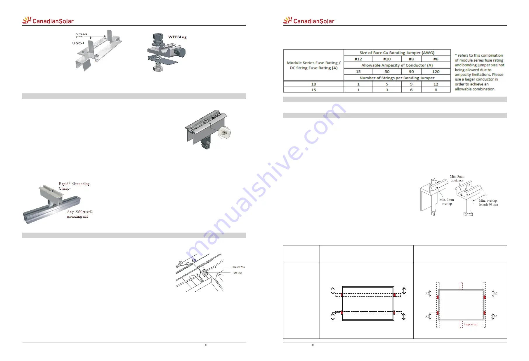
Each Claw to Support, Claw to Claw, and Claw to module connection has been certified by UL to 120A. Determine the
quantity of strings that a bonding jumper connection can accommodate based on the module series fuse rating and
bonding jumper size as below. Verify that all devices used in connecting this bonding jumper can accommodate the
conductor being used.
C.1 MOUNTING METHOD A: CLAMPING
·
·
Top or bottom clamping methods will vary and are dependent on the mounting structures. Follow mounting
guidelines recommended by the mounting system supplier.
·
Each module must be securely fastened at a minimum of 4 points on two opposite sides. The clamps should be
positioned according to the authorized position ranges defined in table B-1. Install and tighten the module clamps to
the mounting rails using the torque stated by the mounting hardware manufacturer. System designer and installer are
responsible for load calculations and for proper design of support structure.
·
Canadian Solar Inc. warranty may be void in cases where improper clamps or unsuitable installation methods are
found. When installing inter-modules or end type clamps, take measures so as:
1.Not to bend the module frame
2.Not to touch or cast shadow on the front glass
3.Not to damage the surface of the frame
4.To ensure the clamps overlap the module frame by at least 5 mm.
5.To ensure the clamps overlap length is at least 40 mm.
·
Clamp material should be anodized aluminum alloy. Floating type
clamps are not authorized.
·
Clamp positions are of crucial importance for the reliability of the
installation, the clamp centerlines must only be positioned within
the ranges indicated in table C-1, depending on the configuration and load as verified by the test method in IEC 61215.
·
For configurations where the mounting rails run parallel to the clamps installation side, precautions should be taken
to ensure the module frame (C-shape) overlap the rail by 15mm or more.
The mounting method has been qualified by Canadian Solar Inc and certified by CSA.
Table C-1: Authorized attachments for clamping method
Clamping on
short side frame
Uplift load
≤
2400 Pa
Downforce load
≤
2400 Pa
Uplift load
2400 Pa
2400 Pa
≤
Downforce load
≤
5400 Pa
≤
Use 4 clamps on the short side, the allowed
range depends on the module type. Mounting
rails may run parallel or perpendicularly to
the short side frame
Use 4 clamps on the short side, the allowed
range depends on the module type. An
additional support bar should be placed
below the module.
Mounting rails should run parallel to the
short side frame
A2
A2
A2
A2
13
·
note
from Canadian Solar for more information. Always follow safety procedures when installing any mounting system.
Failure to follow SolarMount Rail System latest regulatory instructions will void Canadian Solar Inc. module warranty
Refer to the latest
SolarMount Rail System installation manual
from UNIRAC or to
UL-SM_En-A0 Technical
B.4 GROUNDING METHOD D: Grounding Middle Clamps
Used in conjonction with any Schletter module mounting rail (INTERTEK certified)
2+
Schletter Rapid Grounding Clamps are used to create a grounding path
between the module frame and the mounting rail. An integrated grounding
pin ensures bonding to the module frame by penetrating the frame coating.
2+
The Rapid Clamp includes integrated grounding as a standard feature.
2+
·
Rapid Grounding Clamps arrive fully assembled and ready to use. The
15
3
clamps have overall dimensions of 100mm x 35.5mm (3 / in x 1 / in,
16
8
respectively length by width) and are rated to 10 AWG solid copper
conductor wire.
·
To install, simply position the clamp over the mounting rail and insert the pointed clamp end into the rail groove.
Next, tighten the Rapid Grounding Clamp using a standard drill, using a torque of no more than 14.3 Nm (10.5 ft-
lbs) to fasten the clamp hardware (M8x55 Torx and M8 nut). Use of a hammer drill is not recommended.
2+
·
There are always two Rapid Grounding Clamps in contact with any given module, thus ensuring proper and
reliable bonding between the module frame and the mounting rail.
·
2+
·
The quantity of Rapid Grounding Clamps is determined solely by the
module layout. Clamp positions should be strictly determined according
to instructions provided in Annex C of this manual.
2+
·
Refer to
Schletter Rapid Clamp latest installation instructions
for more
information and always follow safety procedures when installing any
2+
mounting system. Failure to follow Rapid Clamp latest regulatory
instructions will void Canadian Solar Inc. module warranty.
B.5 GROUNDING METHOD E: Grounding for Grizzly Bear® FR Gen II SYSTEM
Only for PanelClaw Grizzly Bear® FR Gen II mounting system (INTERTEK certified)
·
are certified under UL Subject 2703 to act as a module and racking equipment
grounding conductor (EGC) device. This certification allows for the Claw to
module and Claw to Support connection to serve the purpose of a copper EGC
that would typically run to each module and Support. When grounding devices
are installed according with the approved methodology and capacity below,
the connections described above meet all the requirements outlined in NEC
690.43.
All PanelClaw mounting attachments or “Claws” have been tested to and
·
A Tyco solid wire grounding assembly, part number 2106831, manufactured by Tyco Electronics Corporation
has been pre-installed on each Grizzly Bear® Support. As you run the copper wire necessary to ground each module
(not provided), ensure the same copper wire is run through every Tyco solid wire grounding assembly and secured
per Tyco Electronics Corporation, LLC specifications (www.te.com). Tighten Tyco solid wire grounding assembly to
torque of 5.08 Nm (45 ft-lb).
·
Locating and Determining the Capacity of an EGC Bonding Jumper: Support locations within the array are
required to be electrically bonded to other DC grounding paths via the use of up to a #6AWG Cu bonding jumper and a
compatible UL 467 listed grounding device.
EN-Rev 2.3 Copyright 20
Canadian Solar Inc.
12 Sep.
EN-Rev 2.3 Copyright 20
Canadian Solar Inc.
12 Sep.
QUALITY I VALUE I INNOVATION
QUALITY I VALUE I INNOVATION