17
Part 6
– Components
6.1
– Electro-Hydraulic Actuator
6.1.1
– Operation
The Electro Hydraulic Actuator mounted on DynaFLO
requires a 24 VAC supply and a 4 to 20mA control signal to
proportionally control the actuator position. The actuators
mounted on DynaFLO have a 3/4-inch (20 mm) stroke. The
actuator communicates with the control through a 4 to 20
mA control signal. The actuator mounted on a valve,
produces a stroke proportional to the input signal. When
power is turned off or in the event of a power failure, the
actuator spring returns the valve to its closed location which
bypasses the heat exchanger.
6.1.2
– Stroke Calibration
To determine the stroke positions 0% and 100% in the
valve, calibration is required when the valve/actuator are
commissioned for the first time. The actuator must be
mechanically connected to a valve and must have a 24 VAC
power supply. The calibration procedure can be repeated
as often as necessary.
WARNING
Before starting calibration, be sure the manual adjuster
is set to automatic to register the actual values.
There is a slot on the printed circuit boards of the actuators.
To initiate the calibration procedure, the contacts inside this
slot must be short-circuited, for example, with a
screwdriver. Automatic calibration can then proceed as
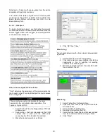
depicted in the following image:
Actuator runs to the 0 stroke position (1), green
LED flashes.
Actuator then runs to the 100 stroke position (2),
green LED flashes.
Measured values are stored in the EPROM.
The actuator now moves to the position defined by
control signal Y or Z (3), and the green LED now
glows steadily (normal operation).
Throughout this procedure, output U is inactive;
meaning, the values only represent actual
positions when the green LED stops flashing and
remains on continuously.
6.1.3
– Manual Operation
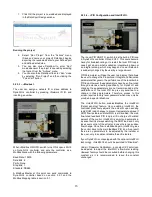
Turn the manual setting knob clockwise for
manual operation.
If a signal is sent to the actuator while it is in
manual operation, the actuator will move but the
control will not be accurate.
The valve cannot be commanded to its 0%
position while in manual operation.
6.2
– Temperature and Pressure Relief Valve (If
Supplied)
6.2.1
– Overview
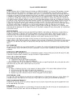
The combined 2-in-1 temperature and pressure relief valve
mounted on DynaFLO provides proven means for
protection against both excessive temperature and
pressure in emergency conditions. It provides full automatic
temperature and pressure relief protection based on the
latest ANSI Z21.22 listing requirements for temperature
discharge capacity.
Содержание DynaFLO DOWB-S1 Series
Страница 2: ......
Страница 25: ...22 Appendix B Electrical Schematics DynaFLO ...
Страница 27: ...24 ...


